
Page 126 - Dynamics and Control of Nuclear Reactors
P. 126
10.8 Steam generator model 121
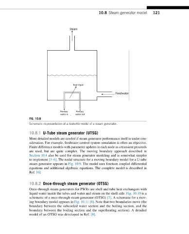
FIG. 10.8
Schematic representation of a teakettle model of a steam generator.
10.8.1 U-Tube steam generator (UTSG)
More detailed models are needed if steam generator performance itself is under con-
sideration. For example, feedwater control system simulation is often an objective.
Finite difference models with parameter updates in each node as a transient proceeds
are used, but are quite complex. The moving boundary approach described in
Section 10.4 also be used for steam generator modeling and is somewhat simpler
to implement [3–6]. The nodal structure for a moving boundary model for a U-tube
steam generator appears in Fig. 10.9. The model uses fourteen coupled differential
equations and additional algebraic equations. The complete model is described in
Ref. [6].
10.8.2 Once-through steam generator (OTSG)
Once-through steam generators for PWRs are shell and tube heat exchangers with
liquid water inside the tubes and water and steam on the shell side. Fig. 10.10 is a
schematic of a once-through steam generator (OTSG) [7]. A schematic for a mov-
ing boundary model appears in Fig. 10.11 [8]. Note that two boundaries move (the
boundary between the subcooled water section and the boiling section, and the
boundary between the boiling section and the superheating section). A detailed
modelofanOTSGwas developedinRef. [8].