
Page 149 - Dynamics and Control of Nuclear Reactors
P. 149
146 CHAPTER 12 Pressurized water reactors
On/Off Heater
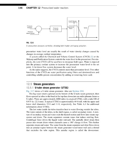
Pressure
Setpoint – Pressure Proportional Spray
Heater
Controller
Pressure +
Measurement
FIG. 12.6
A pressurizer pressure controller, showing both heater and spray actuation.
pressurizer water level are usually the result of water density changes caused by
changes in average coolant temperature.
A system called the Chemical and Volume Control System (CVCS) [1] or the
Makeup and Purification System controls the water level in the pressurizer. For sim-
plicity, the term CVCS will be used here to designate both types. Water is injected
into the primary coolant system to increase the pressurizer water level to the set
point. A let down flow system decreases the water level.
As the name suggests, the CVCS controls more than pressurizer level. Two other
functions of the CVCS are water purification using filters and demineralizers and
controlling soluble poison concentration by adding or removing boric acid.
12.5 Steam generators
12.5.1 U-tube steam generator (UTSG)
Fig. 12.7 shows a U-tube steam generator. Also see Section 10.8.
Hot leg water enters a plenum at the bottom of the U-tube steam generator, then
flows upward in tubes to the bend at the top then down into an outlet plenum (hence a
U-tube). There are approximately 6000 tubes in a typical UTSG, with a tube OD of
0.875-in. (22.1mm). A typical UTSG is approximately 68-ft tall, with the upper and
lower shell diameters 15-ft and 11-ft, respectively. See Table A.1 for additional
information about UTSGs.
The hot water inside the tubes transfers heat to water flowing outside the tubes.
The water outside of the tubes, in the shell region, is called secondary water. A mix-
ture of secondary steam and water exits the heated section and flows into steam sep-
arators and driers. The steam separators contain vanes that induce swirling flow.
Centrifugal force drives the liquid water outward. The partially dried steam then
passes into stream driers where channels cause a 180° change in flow. This further
separates steam and water. The water from the steam separator and drier flows down
into an annular region between the steam generator vessel inner wall and a shroud
that encircles the tube region. This annular region is called the downcomer.