
Page 157 - Dynamics and Control of Nuclear Reactors
P. 157
154 CHAPTER 12 Pressurized water reactors
– Specify the desired values of average coolant temperature at power, P.
– Calculate the average steam temperature using Eq. (12.1).
– Calculate the cold leg temperature using Eq. (12.7).
– Calculate the hot leg temperature using Eq. (12.8).
The above development shows that specification of reactor power and one other var-
iable (average coolant temperature in this example) permits calculation of the other
variables in a steady-state program (T S , θ HL and θ CL ).
The required control rod reactivity is normally not shown in a steady-state pro-
gram, but it is readily calculated using a reactivity balance:
α f T f T f0 + α c θ avg θ avg0 + δρ cont ¼ 0 (12.9)
α f ¼fuel temperature coefficient of reactivity
α c ¼coolant temperature coefficient of reactivity
T f0 ¼fuel temperature at zero power
θ avg0 ¼average coolant temperature at zero power.
A steady-state program with constant average coolant temperature is preferred for
the primary coolant loop because it limits the duty on the pressurizer. A steady state
program with constant average steam temperature is preferred for the steam temper-
ature because it permits optimization of turbine performance. The control policy
being used in practice is a compromise. The coolant average temperature set point
increases with power level; and steam temperature automatically decreases, but not
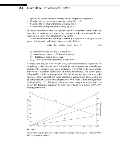
by a large amount. A steady-state program for a PWR with a U-tube steam generator
is shown in Fig. 12.9. The steady-state temperature changes are shown from zero
power (hot functional condition) to 100% power level for a typical 1100 MWe
Westinghouse PWR.
610 900
600
880
Reactor coolant temperature (°F) 580 T out T avg 840 Steam pressure (psia)
P steam
590
860
570
560
820
550
T in
800
540
530 780
0 10 20 30 40 50 60 70 80 90 100
FIG. 12.9
Steady-state program (sliding average temperature program) for a typical 1100MWe PWR
with U-tube steam generators.