
Page 224 - Dynamics and Control of Nuclear Reactors
P. 224
16.2 Sensor characteristics 223
through which it passes. These transit times are measured, and their difference is pro-
portional to the fluid flow rate.
In a magnetic flowmeter, a pipe containing flowing liquid metal is placed
between the poles of a magnet. A voltage is generated by the motion of a conductor
through a magnetic field. Note that electric generators operate on the same principle
(motion of a conductor through a magnetic field).
Eddy current flowmeters are devices containing three coils positioned in the
direction of flow. The middle coil is excited with a constant alternating current. This
current creates induced voltages in the other two coils. When immersed in flowing
liquid metal, the upstream coil’s voltage is less than the downstream coil’s voltage
and this voltage difference is proportional to the fluid flow rate.
Coriolis flowmeters measure mass flow. They are based on the twisting of oscil-
lating flexible tubes caused by the inertia of fluid flowing inside the tubes. The twist-
ing is proportional to the mass flow rate of the fluid.
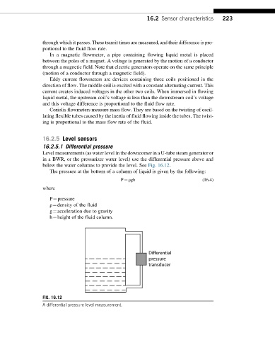
16.2.5 Level sensors
16.2.5.1 Differential pressure
Level measurements (as water level in the downcomer in a U-tube steam generator or
in a BWR, or the pressurizer water level) use the differential pressure above and
below the water columns to provide the level. See Fig. 16.12.
The pressure at the bottom of a column of liquid is given by the following:
P ¼ ρgh (16.4)
where
P¼pressure
ρ¼density of the fluid
g¼acceleration due to gravity
h¼height of the fluid column.
FIG. 16.12
A differential pressure level measurement.