
Page 299 - Dynamics of Mechanical Systems
P. 299
0593_C09_fm Page 280 Monday, May 6, 2002 2:50 PM
280 Dynamics of Mechanical Systems
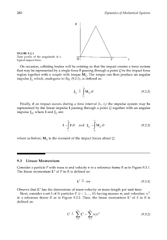
FIGURE 9.2.1
Time profile of the magnitude of a
typical impact force.
On occasion, colliding bodies will be rotating so that the impact creates a force system
that may be represented by a single force F passing through a point Q in the impact force
region together with a couple with torque M . The torque can then produce an angular
Q
impulse J which, analogous to Eq. (9.2.1), is defined as:
Q
t
D
J = ∫ M dt (9.2.2)
Q Q
O
Finally, if an impact occurs during a time interval (t , t ) the impulse system may be
2
1
represented by the linear impulse I passing through a point Q together with an angular
impulse J , where I and J are:
Q
Q
t 2 t 2
I = ∫ Fdt and J Q = ∫ M dt (9.2.3)
Q
t 1 t 1
where as before, M is the moment of the impact forces about Q.
Q
9.3 Linear Momentum
Consider a particle P with mass m and velocity v in a reference frame R as in Figure 9.3.1.
The linear momentum L of P in R is defined as:
P
L = m v (9.3.1)
P D
P
Observe that L has the dimensions of mass–velocity or mass–length per unit time.
Next, consider a set S of N particles P (i = 1,…, N) having masses m and velocities v P i
i
i
S
in a reference frame R as in Figure 9.3.2. Then, the linear momentum L of S in R is
defined as:
N
N
S ∆
L = ∑ L = ∑ m i v P i (9.3.2)
P i
i=1 i=1