
Page 87 - Electric Machinery Fundamentals
P. 87
INTRODUCTION TO MACHINERY PRINCIPLES 63
(c) Assume that the switch shown in the figure is now closed, and calculate the cur-
rent I, the power factor, and the real, reactive, and apparent power being sup-
plied by the source.
(d) How much real, reactive, and apparent power is being consumed by each load
with the switch closed?
(e) What happened to the current flowing from the source when the switch closed?
Why?
+ + +
+
'V V z, 23
( FIGURE PI-14
The circuit of Problem 1-19.
1-20. Demonstrate that Equation (1-59) can be derived from Equation (1- 58) using sim-
ple trigonometric identities.
p(t) ~ v(t)i(t) ~ 2VI cos wI COS(WI - e) (I- 58)
p(t) = VI cos e (l + cos 2Wl) + VI sin e sin 2wt (I-59)
Him: The following identities will be useful:
1
cos a cos [3 ~2 cos (a - [3) + cos (a + [3)]
[
cos (a - (3) = cos a cos f3 + sin O! sin f3
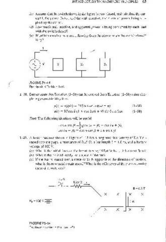
1-21. A linear machine shown in Figure PI- 15 has a magnetic flux density of 0.5 T di-
rected into the page, a resistance of 0.25 n, a bar length I = 1.0 ro, and a battery
voltage of 100 V.
(a) What is the initial force on the bar at starting? What is the initial current flow?
(b) What is the no-load steady-state speed of the bar?
(c) If the bar is loaded with a force of 25 N opposite to the direction of motion,
what is the new steady-state speed? What is the efficiency of the machine under
these circumstances?
1=0
0.250
1 X X X B =0.5 T
X
VB = lOOV-=- 1m
X X X X
FIGURE PI-IS
The linear machine in Problem 1- 21.