
Page 94 - Electric Machinery Fundamentals
P. 94
70 ELECTRIC MACHINERY FUNDAMENTALS
ip (r) is (t)
- '\ -
• • +
\
,
) Np N, IS (t)
)
/
'-
(a)
i, (t)
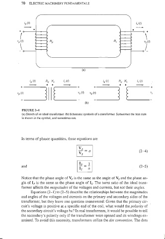
FIGURE 2-4
(a) SkClch of an ideal transformer. (b) Schematic symbols of a lransformer. Sometimes the iron core
is shown in the symbol, and sometimes not.
In terms of phasor quantities, these equations are
EJ (2-4)
Vs
l!e = ! I
and (2-5)
Is a
Notice that the phase angle of V p is the same as the angle of Vs and the phase an-
gIe of Ip is the same as the phase angle of Is. The turns ratio of the ideal trans-
former affects the magnitudes of the voltages and currents, but not their angles.
Equations (2-1) to (2-5) describe the relationships between the magnitudes
and angles of the voltages and cun"ents on the primary and secondary sides of the
transformer, but they leave one question unanswered: Given that the primary cir-
cuit's voltage is positive at a specific end of the coil, what would the polarity of
the secondary circuit's voltage be? In real transformers, it would be possible to tell
the secondary's polarity only if the transformer were opened and its windings ex-
amined. To avoid this necessity, transformers utilize the dot convention. The dots