
Page 273 - Electrical Equipment Handbook _ Troubleshooting and Maintenance
P. 273
GENERATOR COMPONENTS, AUXILIARIES, AND EXCITATION
13.6 CHAPTER THIRTEEN
SEAL FACE
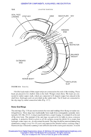
LANDING STOP KEY VANE BACK PLATE KEY
INBOARD
END
GAS
RESTRICTOR
BALANCE
WEIGHT
OUTBOARD
END
ROTOR SHAFT
VENTILATION
SLOT
FIGURE 13.6 Rotor fan.
Flexible leads made of thin copper strips are connected to the ends of the winding. These
leads are placed in two shallow slots in the shaft. Wedges retain them. The leads are con-
nected to radial copper studs, which are connected to D-shaped copper bars placed in the
shaft bore. Hydrogen seals are provided on the radial studs. The D leads are connected to
the slip rings by radial connection bolts (Fig. 13.7).
Rotor End Rings
The end rings (Fig. 13.8) are used to restrain the rotor end windings from flying out under cen-
trifugal forces. These rings have traditionally been made from nonmagnetic austenitic steel,
typically 18% Mn, 4% Cr. A ring is machined from a single forging. It is shrunk-fit at the end
of the rotor body. The material of the end rings was proved to be liable to stress corrosion
cracking. A protective finish is given to all the surfaces except the shrink fit to ensure that
hydrogen, water vapor, etc., do not contact the metal. The rings should be removed during long
maintenance outage (every 8 to 10 years) and inspected for detailed surface cracking using a
fluorescent dye. Ultrasonic scanning is not sufficient due to the coarse grain structure. A recent
Downloaded from Digital Engineering Library @ McGraw-Hill (www.digitalengineeringlibrary.com)
Copyright © 2004 The McGraw-Hill Companies. All rights reserved.
Any use is subject to the Terms of Use as given at the website.