
Page 265 - Electrical Safety of Low Voltage Systems
P. 265
248 Chapter Fifteen
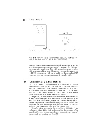
FIGURE 15.5 Schematic representation of distinct grounding electrodes for
sensitive electronic equipment and for 50/60-Hz equipment.
becomes ineffective, circumstance extremely dangerous in TT sys-
tems. The solution to this problem might be to supply the “offender”
equipment with a dedicated RCD with residual operating threshold
set to a sufficiently high value. Alternatively, a separation transformer
withRCDsontheprimarysidecanbeusedtosupplytheload,asRCDs
would not sense any leakage currents on its secondary side.
15.4 Electrical Safety in Train Stations
The typical traction electrification system is composed of overhead
contact lines, a.c. traction power substations, d.c. substations (e.g., at
3 kV d.c.), and a.c./d.c feeders. Both the rails, at a negative poten-
tial, constitute the return path of the d.c. train current to the source
(Fig. 15.6). In some cases, instead of the overhead line a third rail is
employed (e.g., New York City subway, 600 V d.c.).
Should the overhead contact line break and fall, or the pantograph
5
dewire, metal structures (e.g., fences) and publicly exposed equip-
ment (e.g., light poles) in their vicinity may become dangerously en-
ergized. If these items are insulated from ground, or have a high earth
resistance, the fault current might not be large enough to promptly
and safely trip the protective device of the traction line.
6
Thus, for safety reasons, the European Norm EN 50122–1 pre-
scribes that all the ECPs likely to become live due to faults of the
train electrification system must be directly connected to the traction’s
earth, usually the running rails (Fig. 15.7).