Page 85 -
P. 85

ric function of x? What modification to the curve is observed if the degree of
                             the polynomial is increased?


                             Application to a Simple RC Circuit
                             The solution giving the voltage across the capacitor in Figure 3.2 following
                             the closing of the switch can be written in the following form:

                                                                   
                                                                          
                                           Vt( ) =  V ( )exp −0    t  +  V 1 − exp −  t   (3.15)
                                                                               
                                                                   s
                                             c     c        RC          RC
                             V (t) is called the time response of the RC circuit, or the circuit output result-
                              c
                             ing from the constant input V . The time constant RC of the circuit has the
                                                        s
                             units of seconds and, as you will observe in the present analysis and other
                             problems in subsequent chapters, its ratio to the characteristic time of a given
                             input potential determines qualitatively the output of the system.
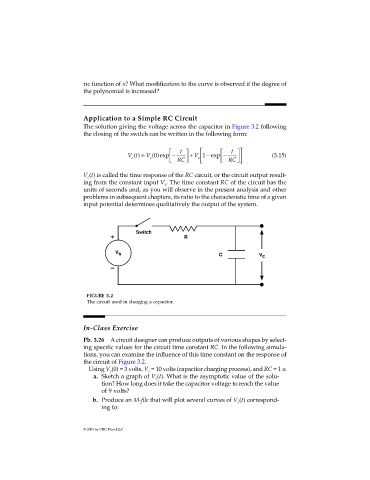


                              FIGURE 3.2
                              The circuit used in charging a capacitor.


                             In-Class Exercise

                             Pb. 3.26 A circuit designer can produce outputs of various shapes by select-
                             ing specific values for the circuit time constant RC. In the following simula-
                             tions, you can examine the influence of this time constant on the response of
                             the circuit of Figure 3.2.
                              Using V (0) = 3 volts, V  = 10 volts (capacitor charging process), and RC = 1 s:
                                                  s
                                     c
                                a. Sketch a graph of V (t). What is the asymptotic value of the solu-
                                                     c
                                   tion? How long does it take the capacitor voltage to reach the value
                                   of 9 volts?
                                b. Produce an M-file that will plot several curves of V (t) correspond-
                                                                                c
                                   ing to:

                             © 2001 by CRC Press LLC
   80   81   82   83   84   85   86   87   88   89   90