
Page 332 - Engineered Interfaces in Fiber Reinforced Composites
P. 332
Chapter 7. Improvement of transverse fracture toughness with interfuw control 313
t L direction
T direction
- Splitting in
longitudinal
lamina
Transverse 1
crack in
transverse (goe)
lamina
0
H'
---J
b 2d b
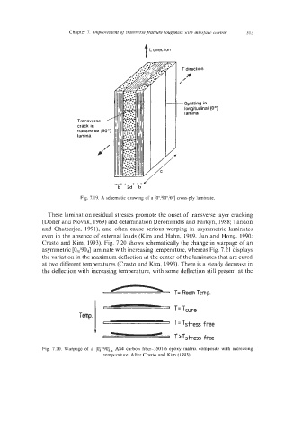
Fig. 7.19. A schematic drawing of a [Oo/9O0/O0] cross-ply laminate
-
These lamination residual stresses promote the onset of transverse layer cracking
(Doner and Novak, 1969) and delamination (Jeronimidis and Parkyn, 1988; Tandon
and Chatterjee, 1991), and often cause serious warping in asymmetric laminates
even in the absence of external loads (Kim and Hahn, 1989, Jun and Hong, 1990;
Crasto and Kim, 1993). Fig. 7.20 shows schematically the change in warpage of an
asymmetric [04/904] laminate with increasing temperature, whereas Fig. 7.2 1 displays
the variation in the maximum deflection at the center of the laminates that are cured
at two different temperatures (Crasto and Kim, 1993). There is a steady decrease in
-
the deflection with increasing temperature, with some deflection still present at the
T=RoomTemp.
Temp. T=Tcure
7 -, T= Tstress free
Fig. 7.20. Warpage of a [0;/90& AS4 carbon fiber-3501-6 epoxy matrix composite with increasing
temperature. After Crasto and Kim (1993).