Page 338 - Engineering Electromagnetics, 8th Edition
P. 338

320                ENGINEERING ELECTROMAGNETICS

                                     are all end-to-end connected, the net loss in dB for the entire span is just the sum of
                                     the dB losses of the individual elements.


                                        D10.2. Two transmission lines are to be joined end to end. Line 1 is 30 m
                                        long and is rated at 0.1 dB/m. Line 2 is 45 m long and is rated at 0.15 dB/m.
                                        The joint is not done well and imparts a 3-dB loss. What percentage of the input
                                        power reaches the output of the combination?

                                        Ans. 5.3%


                                     10.9 WAVE REFLECTION
                                             AT DISCONTINUITIES
                                     The concept of wave reflection was introduced in Section 10.1. As implied there,
                                     the need for a reflected wave originates from the necessity to satisfy all voltage
                                     and current boundary conditions at the ends of transmission lines and at locations
                                     at which two dissimilar lines are connected to each other. The consequences of re-
                                     flected waves are usually less than desirable, in that some of the power that was
                                     intended to be transmitted to a load, for example, reflects and propagates back to
                                     the source. Conditions for achieving no reflected waves are therefore important to
                                     understand.
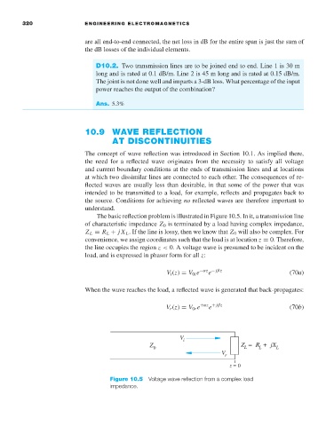
                                        The basic reflection problem is illustrated in Figure 10.5. In it, a transmission line
                                     of characteristic impedance Z 0 is terminated by a load having complex impedance,
                                     Z L = R L + jX L .If the line is lossy, then we know that Z 0 will also be complex. For
                                     convenience, we assign coordinates such that the load is at location z = 0. Therefore,
                                     the line occupies the region z < 0. A voltage wave is presumed to be incident on the
                                     load, and is expressed in phasor form for all z:

                                                              V i (z) = V 0i e −αz − jβz            (70a)
                                                                           e
                                     When the wave reaches the load, a reflected wave is generated that back-propagates:


                                                                           e
                                                              V r (z) = V 0r e +αz + jβz            (70b)


                                                                  V i
                                                         Z 0                         Z  =  R  +  jX L
                                                                                          L
                                                                                      L
                                                                               V r
                                                                                 z = 0

                                             Figure 10.5  Voltage wave reflection from a complex load
                                             impedance.
   333   334   335   336   337   338   339   340   341   342   343