Page 228 - Engineering drawing from first principles using AutoCAD
P. 228

Technical drawings for industry  221

                                      - -
                                      - -
                                       15
                                 4_     -
                                   - -                                                        ~l


                                                                         10----
                                                                                         jl

                                u    -,                                             /
                    o   o             i-}                                      -I      0    0
                    LO   o                                 -              -~            ~    I"-
                    G    (J)           J--                                     --\     G    G
                                l    /                                              "-

                                                                                         "
                                                                         f----


                                                                                               ,~

                                      -               70               -  10 _14 _
                                      -
                                                                       -
                                                                               - -

                                                       PART 4
                                                    COMPONENT


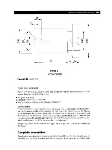
                    Figure 10.20  (continued)


                    Cast iron bracket

                    Figure 10.9 shows the details of a cast iron bracket in first angle projection and we are
                    required to draw the following views:

                  • the given plan view;
                  • a sectional elevation on plane XX;
                  • an end elevation looking in the direction of arrow Y.

                    Solution notes
                    The section plane cuts through the base and vertical web at right angles, so these details
                    are cross-hatched. It also slices through the two thin webs which support the 32mm
                    diameter boss on the right-hand side. The convention is not to cross-hatch thin webs and
                    their outlines are defined as shown. Note that the pitch between the 45° lines on the
                    cross-hatching is the same for all areas as we are only drawing one component. The cross-
                    hatching also covers the MIO thread to the minor diameter.
                    Figure 10.10 shows the solution in first angle, while Figure 10.11 shows the solution in
                    third angle.


                    Complete assemblies

                    Examination questions in engineering drawing invariably involve the draughtsman in
                    assembling components together and drawing two or three views in projection. One
   223   224   225   226   227   228   229   230   231   232   233