
Page 254 - Engineering drawing from first principles using AutoCAD
P. 254
Technical drawinqs for industry 247
Exercise 6: clamp assembly
Copy the dimensioned details of the clamp shown on Fig. 10.30 and then draw the
following assembled views:
• a sectional front elevation
• a plan view.
Note that on the clamp base an arc has been drawn where the 22mm diameter boss
connects with the 34mm diameter post. There is in fact no line here since the fillet
radius does not leave a hard line, but the draughtsman would probably add a line for
completeness, as shading is not a regular practice on engineering drawings. The arc
nearly touches the fillet radii in the front view, and the centre of the arc is projected
up from the plan view. Draw an arc passing through these three points in the front
view.
Choose Arc from the Draw menu. Select 3 Point and the command line reads
Command: _ arc Centre/<Start point>:. Click at the top near the fillet and
command line changes to Centre/End/<Second point>:. Click on the centre line
and the command line changes to End Pain t:. Complete the arc near to the bottom
radii.
Note in the assembly that the bolt, nut and washer are not cross-hatched and the
hatching on the sliding jaw has a closer pitch than the clamp base. Hatching for the
screw threads is from the minor diameter and covers the major diameter. The solution is
drawn in first angle (Fig. 10.31) but a third angle presentation would simply position the
plan view above the section plane.
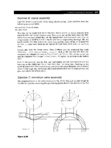
Exercise 7: non-return valve assembly
The component parts of the valve are given in Fig. 10.32. This type of valve would be
installed in a pipeline where liquid or gas was required to flow in one direction only. The
3 o
2
2
o~--+-- 3
Figure 10.36