
Page 283 - Facility Piping Systems Handbook for Industrial, Commercial, and Healthcare Facilities
P. 283
SITE UTILITY SYSTEMS
SITE UTILITY SYSTEMS 6.5
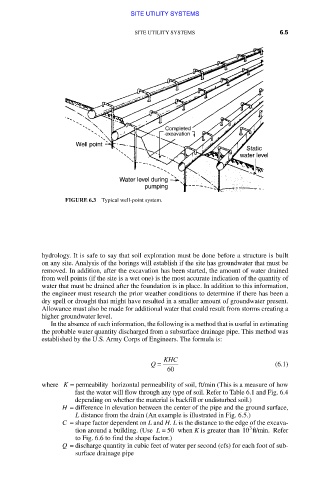
FIGURE 6.3 Typical well-point system.
hydrology. It is safe to say that soil exploration must be done before a structure is built
on any site. Analysis of the borings will establish if the site has groundwater that must be
removed. In addition, after the excavation has been started, the amount of water drained
from well points (if the site is a wet one) is the most accurate indication of the quantity of
water that must be drained after the foundation is in place. In addition to this information,
the engineer must research the prior weather conditions to determine if there has been a
dry spell or drought that might have resulted in a smaller amount of groundwater present.
Allowance must also be made for additional water that could result from storms creating a
higher groundwater level.
In the absence of such information, the following is a method that is useful in estimating
the probable water quantity discharged from a subsurface drainage pipe. This method was
established by the U.S. Army Corps of Engineers. The formula is:
Q = KHC (6.1)
60
where K = permeability horizontal permeability of soil, ft/min (This is a measure of how
fast the water will flow through any type of soil. Refer to Table 6.1 and Fig. 6.4
depending on whether the material is backfill or undisturbed soil.)
H = difference in elevation between the center of the pipe and the ground surface,
L distance from the drain (An example is illustrated in Fig. 6.5.)
C = shape factor dependent on L and H. L is the distance to the edge of the excava-
3
tion around a building. (Use L = 50 when K is greater than 10 ft/min. Refer
to Fig. 6.6 to find the shape factor.)
Q = discharge quantity in cubic feet of water per second (cfs) for each foot of sub-
surface drainage pipe
Downloaded from Digital Engineering Library @ McGraw-Hill (www.accessengineeringlibrary.com)
Copyright © 2009 The McGraw-Hill Companies. All rights reserved.
Any use is subject to the Terms of Use as given at the website.