
Page 139 - Failure Analysis Case Studies II
P. 139
124
RF*IN --
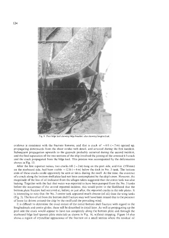
Fig. 9. Port bilge keel showing bilge bracket: also showing longitudinal
evidence is consistent with the fracture features, and that a crack of -6ft (-2m) opened up,
propagating downwards from the sheer strakeweb detail, and arrested during the first incident.
Subsequent propagation upwards to the gunwale probably occurred during the second incident,
and the final separation of the two sections of the ship involved the joining of the arrested 6 ft crack
and the crack propagated from the bilge keel. This process was accompanied by the deformation
shown in Fig. 13.
After the first reported noises, two cracks 6 ft (- 2 m) long on the port side, and 6 in. (1 50 mm)
on the starboard side, had been visible - 12 ft (-4 m) below the deck in No. 3 tank. The bottom
ends of these cracks could apparently be seen at times during the swell. At the time, the existence
of a crack along the bottom shell plate had not been contemplated by the ship’s crew. However, the
magnitude of the loss of oil indicated from the ullages taken suggested that the centre tank was also
leaking. Together with the fact that water was reported to have been pumped from the No. 3 tanks
before the occurrence of the second reported incident, this would point to the likelihood that the
bottom plate fracture had occurred at, before, or just after, the reported cracks in the side plates. It
is interesting to note that the No. 3 centre tank appeared much cleaner (of oil) than the wing tanks
(Fig. 5). The loss of oil from the bottom shell fracture may well have been missed due to the presence
of loose ice driven around the ship by the swell and the prevailing wind.
It is difficult to determine the exact extent of the initial bottom shell fracture with regard to the
longitudinals and centre girder, these will be described in detail later. As well as propagating up the
port side the crack would appear to have run completely along the bottom plate and through the
starboard bilge keel (parent plate material) as shown in Fig. 14, without stopping. Figure 14 also
shows a region of crystalline appearance of the fracture on a small section where the residual oil