
Page 382 - Fiber Bragg Gratings
P. 382
8.1 Fiber grating semiconductor lasers: The FGSL 359
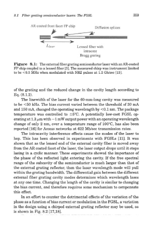
Figure 8.1: The external fiber grating semiconductor laser with an AR-coated
FP chip coupled to a lensed fiber [3]. The measured chirp was instrument limited
to be <0.5 MHz when modulated with NRZ pulses at 1.2 Gb/sec [15].
of the grating and the reduced change in the cavity length according to
Eq. (8.1.2).
The linewidth of the laser for the 60-mm-long cavity was measured
to be <50 kHz. The bias current varied between the threshold of 30 mA
and 150 mA, changed the operating wavelength by < 0.1 nm. The package
temperature was controlled to ±5°C. A potentially low-cost FGSL op-
erating at 1.3 yam with ~ 1 mW output power with an operating wavelength
change of only 2 nm, over a temperature range of 100°C, has also been
reported [16] for Access networks at 622 Mb/sec transmission rates.
The intracavity interference effects cause the modes of the laser to
hop. This has been observed in experiments with FGSLs [11]. It was
shown that as the lensed end of the external cavity fiber is moved away
from the AR coated facet of the laser, the laser output drops until it stops
lasing in a cyclic manner. These experiments showed the importance of
the phase of the reflected light entering the cavity. If the free spectral
range of the subcavity of the semiconductor is much larger than that of
the external grating reflector, then the laser wavelength mode will pull
within the grating bandwidth. The differential gain between the different
external fiber grating cavity modes determines which wavelength lases
at any one time. Changing the length of the cavity is similar to changing
the bias current, and therefore requires some mechanism to compensate
this effect.
In an effort to counter the detrimental effects of the variation of the
phase as a function of bias current or modulation in the FGSL, a variation
in the design using a chirped external grating reflector may be used, as
is shown in Fig. 8.2 [17,18].