
Page 202 - Fiber Fracture
P. 202
STRENGTH AND FRACTURE OF METALLIC FILAMENTS 187
state of stress die
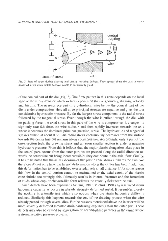
Fig. 2. State of stress during drawing and central bursting defects. They appear along the axis in work-
hardened wires when metals become unable to sufficiently yield.
of the conical part of the die (Fig. 2). The flow pattern in this zone depends on the local
state of the stress deviator which in turn depends on the die geometry, drawing velocity
and friction. The near-surface part of a cylindrical wire below the conical part of the
die is under compression. Here all three principal stresses are negative and give rise to a
considerable hydrostatic pressure. By far the largest stress component is the radial stress
followed by the tangential stress. Even though the wire is pulled through the die, with
no pushing force, the axial stress in this part of the wire is compressive. It changes its
sign only near 0.6 times the wire radius r and then rapidly increases towards the axis
where it becomes the dominant principal (traction) stress. The hydrostatic and tangential
stresses vanish at about 0.3r. The radial stress continuously decreases from the surface
towards the center line but remains always compressive. Accordingly, only a part of the
cross-section feels the drawing stress and an even smaller section is under a negative
hydrostatic pressure. From this it follows that the major plastic elongation takes place in
the central part. Atoms from the outer portion are pressed along the radial direction to-
wards the center line but being incompressible, they contribute to the axial flow. Finally,
it has to be noted that the axial extension of the plastic zone shrinks towards the axis. We
therefore do not only have the largest deformation along the center line but, in addition,
this deformation has to be established over a relatively small distance. If for some reason
this flow in the central portion cannot be maintained or the axial extent of the plastic
zone shrinks too strongly, this ultimately results in internal fractures and the formation
of voids whose cup- or chevron-like form reflects the velocity field near the axis.
Such defects have been explained (Avitzur, 1980; Mielnik, 1991) by a reduced strain
hardening capacity as occurs in already strongly deformed metal. It resembles closely
the necking in a tensile test which also occurs when the strain hardening ability is
reduced. Similarly, this happens towards the end of the drawing process when the wire
already passed through several dies. For the reasons mentioned above the interior will be
more severely deformed (smaller strain hardening exponent) than the outer part. These
defects may also be caused by segregation or second-phase particles in the range where
a strong negative pressure prevails.