
Page 310 - Finite Element Modeling and Simulations with ANSYS Workbench
P. 310
Structural Vibration and Dynamics 295
Carefully build your FE mesh (using shell elements) so that the symmetry of the
tank is reserved and the boundary conditions in part (b) can be applied readily.
Assume the tank is made of steel with Young’s modulus E = 200 GPa, Poisson’s
ratio ν = 0.3, and mass density ρ = 7850 kg/m .
3
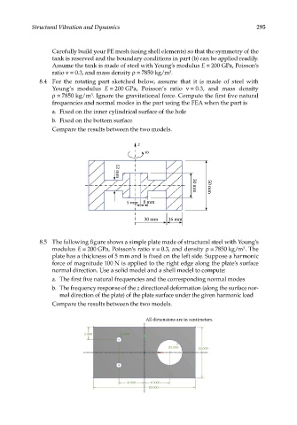
8.4 For the rotating part sketched below, assume that it is made of steel with
Young’s modulus E = 200 GPa, Poisson’s ratio ν = 0.3, and mass density
ρ = 7850 kg/m . Ignore the gravitational force. Compute the first five natural
3
frequencies and normal modes in the part using the FEA when the part is
a. Fixed on the inner cylindrical surface of the hole
b. Fixed on the bottom surface
Compare the results between the two models.
z
12 mm
5 mm 8 mm 30 mm 50 mm
30 mm 16 mm
8.5 The following figure shows a simple plate made of structural steel with Young’s
3
modulus E = 200 GPa, Poisson’s ratio ν = 0.3, and density ρ = 7850 kg/m . The
plate has a thickness of 5 mm and is fixed on the left side. Suppose a harmonic
force of magnitude 100 N is applied to the right edge along the plate’s surface
normal direction. Use a solid model and a shell model to compute:
a. The first five natural frequencies and the corresponding normal modes
b. The frequency response of the z directional deformation (along the surface nor-
mal direction of the plate) of the plate surface under the given harmonic load
Compare the results between the two models.
All dimensions are in centimeters.
5.000 R1.000
R5.000 20.000
10.000 10.000
40.000