
Page 298 - Fluid-Structure Interactions Slender Structure and Axial Flow (Volume 1)
P. 298
PIPES CONVEYING FLUID: NONLINEAR AND CHAOTIC DYNAMICS 279
1981), the equations of motion were derived ab initio, and hence several sets of different
and certainly different-looking equations have come into existence. How different, and
how complete and correct? The answering of these questions is not a trivial task, because
of the different notations, approaches and assumptions involved in each of the derivations,
and the relative obscurity of some. Hence, a definitive comparison was not undertaken
until recently (Semler et al. 1994), but not before a number of de facto ‘schools’ had
developed, followers of each utilizing the same basic assumptions and similar final forms
of the equations.
In this section, following closely Semler et al. (1994), the equations of motion
are derived via a Hamiltonian approach (while a Newtonian derivation is outlined
in Appendix G) and, then, those of others’ are discussed and their completeness and
correctness assessed.
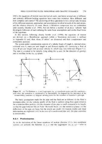
The system under consideration consists of a tubular beam of length L, internal cross-
sectional area A, mass per unit length m and flexural rigidity Ef, conveying a fluid of
mass M per unit length with an axial velocity U, which may vary with time (Figure 5.1).
The pipe is assumed to be initially lying along the xo-axis (in the direction of gravity)
and to oscillate in the (xg, ZO) plane.
Figure 5.1 (a) The Eulerian (x, z) and Lagrangian (xo, zo) coordinate system and the coordinate s
used when the centreline is considered to be inextensible; (b) diagram for the derivation of the
inextensibility condition; (c) diagram defining terms for the statement of Hamilton’s principle.
The basic assumptions made for the pipe and the fluid are as follows: (i) the fluid is
incompressible; (ii) the velocity profile of the fluid is uniform (plug-flow approximation
for a turbulent-flow profile); (iii) the diameter of the pipe is small compared to its length,
so that the pipe behaves like an Euler-Bernoulli beam; (iv) the motion is planar; (v) the
deflections of the pipe are large, but the strains are small; (vi) rotatory inertia and shear
deformation are neglected; (vii) in the case ofa cantilevered pipe only, the pipe centreline
is inextensible.
5.2.1 Preliminaries
As in the derivation of the linear equations of motion (Section 3.3.1), two coordinate
systems are utilized: the Eulerian (x, y, z) and the Lagrangian (xg, yo, ZO) - refer to