
Page 460 - Fluid-Structure Interactions Slender Structure and Axial Flow (Volume 1)
P. 460
432 SLENDER STRUCTURES AND AXIAL FLOW
(6.78)
4- E2 ([N3]1T([N3]”’ + 02[N3]’) - @2[N3]T([N3]’r + O2[N3])}
I
a
+ [N31’T -[n0([N31” + 02[N31)1 - @2n0[N31T([N31” + O2[N3]) d<;
at
<e is the length of the element under consideration. The highest order derivative of [N3]
appearing in these expressions is the third. Hence, it is necessary to ensure that q:, q;’
and ,I$” be continuous between elements, which is achieved if the nodal displacements
Thus, for an element of the pipe
at each node are taken as values of qj, r;’ and $’I.
(Figure 6.4) with a node j at one end and a node j + 1 at the other,
*I/ T
(qiJj = {$,j, q3.j 9 r3,j 1 (6.79)
*I
and
(6.80)
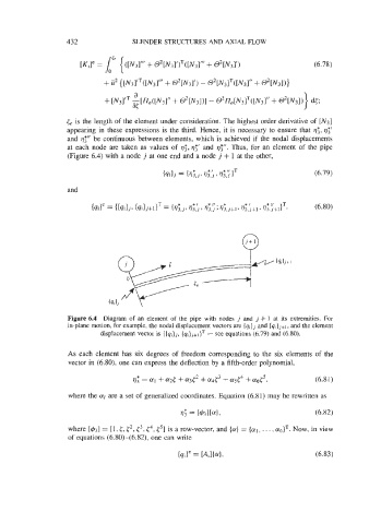
Figure 6.4 Diagram of an element of the pipe with nodes j and j + 1 at its extremities. For
in-plane motion, for example, the nodal displacement vectors are (qjj and (qijj+], and the element
displacement vector is {q,)j+l)T - see equations (6.79) and (6.80).
As each element has six degrees of freedom corresponding to the six elements of the
vector in (6.80), one can express the deflection by a fifth-order polynomial,
r; = a1 + azt + a3t2 + ad3 + ad4 + agt5, (6.81)
where the ai are a set of generalized coordinates. Equation (6.81) may be rewritten as
where [&I = 11, <, c2, t3, q4, c5I is a row-vector, and (a} = (al, . . . , Now, in view
of equations (6.80)-(6.82), one can write