
Page 32 - Fluid mechanics, heat transfer, and mass transfer
P. 32
VISCOSITY MEASUREMENT 9
➢ In this device, a concentric rotating cylinder
(spindle) spins at a constant rotational speed inside
another cylinder. In general, there is a very small
gap between the walls. This annulus is filled with
the fluid. The torque needed to maintain this
constant rotation rate of the inner spindle is mea-
sured by means of a torsion wire from which the
spindle is suspended. This device is sometimes
called Couette viscometer, named after its discov-
erer. Some types of viscometers rotate the outer
cylinder.
& Cup and bob viscometers (Figure 1.4) work by
defining the exact volume of sample that is to be
sheared within a test cell; the torque required to
achieve a certain rotational speed is measured and
plotted. There are two classical geometries in cup and
bob viscometers known as either the Couette or
Searle systems—distinguished by whether the cup
or bob rotates.
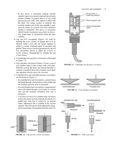
& A Cambridge moving piston viscometer is illustrated
in Figure 1.5.
& Cone and plate viscometers (Figure 1.6) use a cone of
Cambridge moving piston viscometer.
very shallow angle in bare contact with a flat plate. FIGURE 1.5
With this system, the shear rate beneath the plate is
constant. A graph of shear stress (torque) versus shear
rate (angular velocity) gives the viscosity.
& Controlled flow and controlled pressure viscometers
are illustrated in Figure 1.7.
➢ In controlled flow rate viscometers, a piston forces
the liquid through a horizontal or vertical tube and
the resultant pressure drop is measured.
➢ In controlled pressureviscometers, compressed air
drives the liquid through a horizontal or vertical Cone and plate viscometers.
FIGURE 1.6
tube and the resultant volumetric flow rate is
measured.
➢ A Stormer viscometer is a rotation-type viscometer
used to determineviscosity of paints. It consists of a
paddle-type rotor that is rotated by an internal
motor, submerged into a cylinder of the viscous
material. The rotor speed can be adjusted by chang-
ing themagnitude ofloadappliedonto therotor.For
Cup and bob coaxial viscometers. Tube viscometers.
FIGURE 1.4 FIGURE 1.7