
Page 54 - Fluid mechanics, heat transfer, and mass transfer
P. 54
WATER HAMMER 31
branch, or tracer line or pumped condensate lines or & A pressure wave as a result of a pump stopping is
heat exchanger tubing. Steam will collapse, since more damaging than a pump starting due to the large
condensate temperature is mostly subcooled in the change in pressure that will continue much longer
lines. after the pump is stopped, compared to start of the
➢ This collapse will release energy in a short period pump.
of time. & Entrained air or temperature changes of the water can
➢ Vacuum is created due to suddenvolume reduction be controlled by pressure relief valves, which are set
by about 1600 times. to open with excess pressure in the line and then
➢ Water rushes into this space from all directions. closed when pressure drops. Relief valves are com-
monly used in pump stations to control pressure
& Flow Shock: Caused by lack of proper drainage
surges and to protect the pump station. Positively
ahead of a steam line isolation valve or steam control
controlled relief valves act as surge suppressors.
valve.
These valves can be an effective method of control-
➢ Changes in power demand from turbines.
ling transients.
➢ Operation of reciprocating pumps.
& However, they must be properly sized and selected.
➢ Changing elevation of a reservoir/storage tank.
& Where pressure drops due to condensation or un-
➢ Waves on a reservoir.
loading operations, giving rise to vacuum in the sys-
➢ Unstable fan or pump characteristics. tem, properly selected and sized vacuum breaker–air
➢ Tube failure in a heat exchanger. release valves can be the least expensive means of
. What are the important phenomenon parameters useful protecting a piping system.
in the analysis of water hammer? & Pump start-up problems can usually be avoided by
increasing the flow slowly to collapse or flush out the
& Velocity of the pressure wave.
voids gently. Also, a simple means of reducing
& Critical time of the phenomenon.
hydraulic surge pressure is to keep pipelinevelocities
& Maximum head developed in the maximum pressure
low. This not only results in lower surge pressures,
time.
but also results in lower drive horsepower and, thus,
& Minimum head developed in the critical time. maximum operating economy.
. What are the precautions to prevent or reduce water & Providing surge tanks in long pipelines to relieve
hammer? pressures generated, storing excess liquid. These
& Designing the system with low velocities. tanks can serve as dampeners for both positive and
& Water hammer often damages centrifugal pumps negative pressures. However, surge tanks for surge
when electric power fails. In this situation, the best control are expensive compared to other devices.
form of prevention is to have automatically con- & Since severity of water hammer is highly dependent
trolled valves, which close slowly. (These valves on the acoustic velocity, a reduction in acoustic
work without electricity or batteries. The direction velocity will reduce hammer. This can be accom-
of the flow controls them.) Closing the valve slowly plished by adding a small quantity of air to a liquid
can moderate the rise in the pressure when the down- system or switching to noncircular piping.
surge wave, resulting from the valve closing, returns & Installing air chambers in systems with frequent
from the reservoir. water hammer problems: shaped like thin, upside-
& Providing slow closing bypasses around fast closing down bottles with a small orifice connection to the
valves. pipe, they are air-filled. The air compresses to absorb
& Ensuring correct flow directions in the process plant the shock, protecting the fixture and piping.
can reduce or even prevent pressure wave problems.
& With air-operated seat valves, incorrect direction of
flow can cause the valve plug to close rapidly against
the valve seat inducing pressure waves.
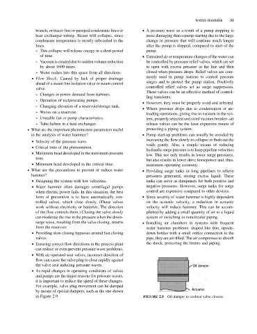
& As rapid changes in operating conditions of valves
and pumps are the major reasons for pressure waves,
it is important to reduce the speed of these changes.
For example, valve plug movement can be damped
by means of special dampers, such as the one shown
in Figure 2.9. FIGURE 2.9 Oil damper to cushion valve closure.