
Page 235 - Fluid-Structure Interactions Slender Structure and Axial Flow (Volume 1)
P. 235
216 SLENDER STRUCTURES AND AXIAL FLOW
at x = L. All quantities are the same as in Section 3.3.2, but some new ones need be
introduced: Ma is the added mass of the pipe per unit length; % is the end-mass, of mass-
moment of inertia 7, and centre of mass at a distance 2 from the pipe end (x = L); Fb is
the buoyancy force associated with %; cy2 = A,/Aj = U,/U is the ratio of external pipe
area to inlet jet area, with Uj as shown in Figure 4.12(b); po~ is the external, hydrostatic
pressure at x = L; other barred quantities have the same meaning as plain ones, but are
associated with the end-mass. A form of expression (2.157) is used for c - see also
equation (3.106). Furthermore, assuming a spherical form for z, C = 6nvpd, where v is
the kinematic viscosity of the fluid.
It is stressed that in this formulation, in accordance with Figure 4.12(b), a positive U
corresponds to up--ow, i.e. to what in Section 4.3.1 is called a negative flow velocity.
For very long pipes, a pipe-string approximation is normally used, i.e. the flexural
rigidity is ignored; however, here flexural terms are retained. Because of the fact that the
boundary conditions are frequency-dependent, the usual form of the Galerkin method is
not applicable to this case (see also Section 4.6.2). A special hybrid Fourier-Galerkin
method developed by Hannoyer (1972), outlined in Chapter 8, is used instead.
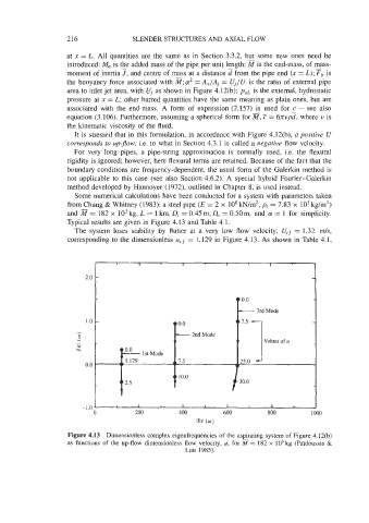
Some numerical calculations have been conducted for a system with parameters taken
from Chung & Whitney (1983): a steel pipe (E = 2 x IOs kNm2, pr = 7.83 x IO3 kg/m3)
and a = 182 x lo3 kg, L = 1 km, Di = 0.45 m, Do = 0.50m, and cy = 1 for simplicity.
Typical results are given in Figure 4.13 and Table 4.1.
The system loses stability by flutter at a very low flow velocity, U,, = 1.32 m/s,
corresponding to the dimensionless u,.f = 1.129 in Figure 4.13. As shown in Table 4.1,
I .o
0.0
-1.0 1 1 1 1 I 1 1
0 200 400 600 800 loo0
(w)
Figure 4.13 Dimensionless complex eigenfrequencies of the aspirating system of Figure 4.12(b)
as functions of the up-flow dimensionless flow velocity, u, for = 182 x lo3 kg (Pai'doussis &
Luu 1985).