
Page 78 - Fluid-Structure Interactions Slender Structure and Axial Flow (Volume 1)
P. 78
PIPES CONVEYING FLUID: LINEAR DYNAMICS I 61
1.
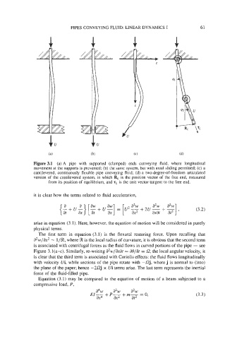
Figure 3.1 (a) A pipe with supported (clamped) ends conveying fluid, where longitudinal
movement at the supports is prevented; (b) the same system, but with axial sliding permitted; (c) a
cantilevered, continuously flexible pipe conveying fluid; (d) a two-degree-of-freedom articulated
version of the cantilevered system, in which RL is the position vector of the free end, measured
from its position of equilibrium, and IL is the unit vector tangent to the free end.
it is clear how the terms related to fluid acceleration,
(;+U~}[$+Ug] = [U ,,+ZU-+- (3.2)
a2w
axat a2w at2 ’
arise in equation (3.1). Here, however, the equation of motion will be considered in purely
physical terms.
The first term in equation (3.1) is the flexural restoring force. Upon recalling that
a2w/ax2 - l/%, where 3 is the local radius of curvature, it is obvious that the second term
is associated with centrifugal forces as the fluid flows in curved portions of the pipe - see
Figure 3.l(a-c). Similarly, re-writing a2w/axat = %/at = a, the local angular velocity, it
is clear that the third term is associated with Coriolis effects: the fluid flows longitudinally
with velocity Ui, while sections of the pipe rotate with -Qj, where j is normal to (into)
the plane of the paper; hence -2Qj x Ui terms arise. The last term represents the inertial
force of the fluid-filled pipe.
Equation (3.1) may be compared to the equation of motion of a beam subjected to a
compressive load, P,
a2w
a4pv a2w
EI- + P- +m-- = 0, (3.3)
a.r4 ax2 at2