
Page 108 - Forensic Structural Engineering Handbook
P. 108
DESIGN CODES AND STANDARDS 2.13
may be used in place of the applicable sections of the current Code. Regardless of whether the
strength design method of the Code or the alternate design method is used in proportioning for
strength, the general serviceability requirements of the Code, such as the provisions for
deflection control and crack control, must always be satisfied.
According to ACI 318, the required strength provided to resist dead load D and live load
L must be at least equal to
U =1.2D + 1.6L
If a wind load W must be considered, the following combinations of D, L, and W should be
investigated:
U = 1.2D + 1.6W + 1.0L
U = 0.9D + 1.6W
The second equation must be checked for two cases: (1) the live load L, equal to its full
value and (2) L = 0. In any case, the strength of the member or structure must not be less
than required by the first equation.
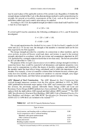
The design strength provided by a member, its connections to other members, and its
cross sections, in terms of flexure, axial load, shear, and torsion, is equal to the nominal
strength calculated in accordance with the provisions and assumptions stipulated in ACI
318, multiplied by a strength reduction factor that is less than unity. The factors prescribed
by ACI are identified in Table 2.2.
The purpose of the strength reduction factor f is to define a design strength level that is
somewhat lower than would be expected if all dimensions and material properties were
those used in computations; to reflect the degree of ductility, toughness, and reliability of
the member under the load effects being considered; and to reflect the importance of the
member. For example, a lower f is used for columns than for beams because columns gen-
erally have less ductility, are more sensitive to variations in concrete strength, carry larger
loaded areas than beams, and their failure precipitates greater damage.
AISC Manual of Steel Construction. The AISC Manual for Steel Construction has
evolved through numerous versions from the first edition, published in 1923. In 2005,
26
AISC published the thirteenth major update of the AISC steel construction manual. With
this revision, the previously separate Allowable Stress Design (ASD) and Load and
Resistance Factor Design (LRFD) methods have been combined. Thus, the thirteenth edition
replaces both the ninth edition ASD manual and third edition LRFD manual. 27,28 The 2005
AISC Specification for Structural Steel Buildings, 2005 AISC Code of Standard Practice For
Steel Buildings and Bridges, and 2004 RCSC Specification for Structural Joints Using
ASTM A325 or A490 Bolts are included in the manual. 29–31
TABLE 2.2 ACI 318-95 Capacity Reduction Factors
Type of stress
Axial tension, and bending with or without axial tension 0.90
Axial compression with or without bending:
Members with spiral reinforcement 0.75*
Other reinforced members 0.65*
Shear and torsion 0.75
Bending in plain concrete 0.65
*May be increased linearly to 0.90 in accordance with Sec. 9.3.2.