
Page 544 - Forensic Structural Engineering Handbook
P. 544
14.34 MATERIAL-SPECIFIC FORENSIC ANALYSES
Compressive buckling of the unrestrained arch, due to inadequate bracing, is considered
to be the sole cause of failure. Arches ahead of the decking/diaphragm placement had
inadequate or nonexistent lateral bracing. The rapid collapse also suggests buckling,
whereas flexural failure is usually accompanied by noise and incremental movements over
a period of time. The arena was rebuilt per the original design.
Case Study 7. Port Hadlock Post Office, Port Hadlock, Washington
This case study illustrates eccentric connection, truss bracing, and buckling. When light-
framed timber trusses collapse under construction, it is usually the result of insufficient
bracing. That was considered the cause by the truss company’s representatives. In this case
the bracing did not quite meet the specified criteria of the truss company, thus giving them
a significant legal advantage. However, the author determined it was not the primary cause
of collapse and probably would not have prevented the collapse of the trusses had the spec-
ified bracing criteria been fully met.
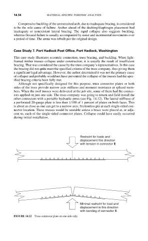
Although not specifically designed for this purpose, truss connector plates or both
sides of the truss provide narrow axis stiffness and moment resistance at spliced mem-
bers. When the roof trusses were delivered at the job site, some of them had the connec-
tors applied on just one side. The truss company was going to return and field install the
other connectors with a portable hydraulic press (see Fig. 14.12). The lateral stiffness of
a perforated 20-gauge plate is less than 1/100 of 1 percent of plates on both faces. This
is about as close as one can get to a narrow axis, frictionless pin at each single-sided con-
nector location. These trusses would be unstable unless a brace were placed at, or adja-
cent to, each of the single-sided connector plates. Collapse could have easily occurred
during initial installation.
Restraint for loads and
displacement this direction
with tension in connector PL
Minimal restraint for load and
displacement in this direction
with bending of connector PL
FIGURE 14.12 Truss connector plate on one side only.