
Page 268 - Fundamentals of Enhanced Oil and Gas Recovery
P. 268
256 Alireza Keshavarz et al.
Figure 8.5 Effect of proppant concentration and confining stress on fracture conductivity. After
Khanna, A., Keshavarz, A., Mobbs, K., Davis, M., Bedrikovetsky, P., 2013. Stimulation of the natural frac-
ture system by graded proppant injection. J. Pet. Sci. Eng. 111, 71 77.
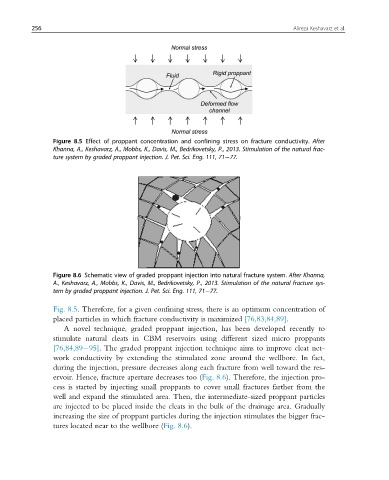
Figure 8.6 Schematic view of graded proppant injection into natural fracture system. After Khanna,
A., Keshavarz, A., Mobbs, K., Davis, M., Bedrikovetsky, P., 2013. Stimulation of the natural fracture sys-
tem by graded proppant injection. J. Pet. Sci. Eng. 111, 71 77.
Fig. 8.5. Therefore, for a given confining stress, there is an optimum concentration of
placed particles in which fracture conductivity is maximized [76,83,84,89].
A novel technique, graded proppant injection, has been developed recently to
stimulate natural cleats in CBM reservoirs using different sized micro proppants
[76,84,89 95]. The graded proppant injection technique aims to improve cleat net-
work conductivity by extending the stimulated zone around the wellbore. In fact,
during the injection, pressure decreases along each fracture from well toward the res-
ervoir. Hence, fracture aperture decreases too (Fig. 8.6). Therefore, the injection pro-
cess is started by injecting small proppants to cover small fractures farther from the
well and expand the stimulated area. Then, the intermediate-sized proppant particles
are injected to be placed inside the cleats in the bulk of the drainage area. Gradually
increasing the size of proppant particles during the injection stimulates the bigger frac-
tures located near to the wellbore (Fig. 8.6).