
Page 33 - Fundamentals of Enhanced Oil and Gas Recovery
P. 33
An Introduction to Enhanced Oil Recovery 21
where
DP is differential pressure across the capillary tube
μ is viscosity of flowing fluid
L is tube length
V is average velocity in tube
1.13 PORE SCALE TRAPPING, MOBILIZATION OF TRAPPED OIL
During primary and secondary production some parts of oil remain in the reser-
voir. From a microscopic point of view, this oil is trapped in the pores surrounded with a
second fluid. The trapping mechanism depends on the pore geometry, rock wettability,
and interfacial tension. These parameters govern fluid trapping and mobilization through
porous media. Here, trapping mechanisms are investigated in some simplified models.
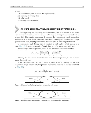
In some cases a high driving force is required to push a globe of oil trapped in a
tube. Fig. 1.8 shows the schematic of an oil drop in a tube surrounded with water.
By assuming a constant pressure profile in the oil drop, it can be written that:
2σ ow cosθ 2σ ow cosθ
P B 2 P A 5 2
r r
A B
Although the oil pressure would be more than the water pressure, the net pressure
along the tube is zero.
In the case of difference in contact angles at points A and B, receding and advanc-
ing contact angles respectively, the pressure required to mobilize oil can be calculated
as (Fig. 1.9):
2σ ow
P B 2 P A 5 ð cosθ A 2 cosθ B Þ
r
Figure 1.8 Schematic of oil drop in a tube surrounded with water.
Figure 1.9 Difference in contact angles in oil drop in a tube surrounded with water.