
Page 124 - Fundamentals of Magnetic Thermonuclear Reactor Design
P. 124
108 Fundamentals of Magnetic Thermonuclear Reactor Design
fore important to arrange properly the modelling process as a sequence of
steps.
For the ITER machine, it seems reasonable to use the ‘VV + TS + CR’ shell
model as a global computation model (Figs. A.4.2.2 and A.4.2.3). There are
several ways to integrate other computation models for the structures of interest
with the global one. They include the following:
l Incorporation of local shell models of the structures into the global model.
l Account for the EM impact of the field sources described with the global
model in the models used for EM analyses of other reactor systems.
l Solution of a local problem with a detail description of conductive structures
within a closed subdomain. Distributions of fields from external current
sources, eddy currents, or respective potentials are given on the subdomain
boundary. A global shell model and various local models may be applied to
compute those fields, currents and potentials.
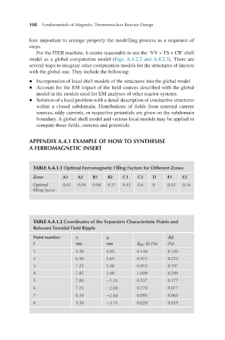
APPENDIX A.4.1 EXAMPLE OF HOW TO SYNTHESISE
A FERROMAGNETIC INSERT
TABLE A.4.1.1 Optimal Ferromagnetic Filling Factors for Different Zones
Zone A1 A2 B1 B2 C1 C2 D E1 E2
Optimal 0.02 0.04 0.08 0.27 0.43 0.6 0 0.32 0.16
filling factor
TABLE A.4.1.2 Coordinates of the Separatrix Characteristic Points and
Relevant Toroidal Field Ripple
Point number r i z i δ(i)
I (m) (m) δ TFC (i) (%) (%)
1 5.50 4.05 0.148 0.120
2 6.50 3.65 0.472 0.223
3 7.25 3.00 0.813 0.197
4 7.85 2.00 1.009 0.289
5 7.80 −1.15 0.537 0.177
6 7.25 −2.00 0.278 0.077
7 6.50 −2.60 0.095 0.065
8 5.50 −3.15 0.020 0.019