
Page 242 - Fundamentals of Magnetic Thermonuclear Reactor Design
P. 242
First Wall Components Chapter | 7 223
ments for the cooling channels are strength and leak-tightness. We remember
that in ITER, the coolant’s pressure limit is 4 MPa in normal conditions and
6 MPa in test conditions. Channels with ∼2-mm walls seem to be suitable.
For a flat FW with round-cross-section cooling channels, the maximum joint
temperature is determined by the interchannel space and distance from a channel
centre to the joint point equidistant from neighbouring channels. These distances
must be as small as possible. To achieve this, it would be good to have cooling
channels with a rectangular cross section. So, minimum joint temperature T , de-
min
pending on heat load, is in the 100°C–400°C window for different FW components.
The material and thickness of the armour tiles are selected using the follow-
ing criteria. Surface maximum temperature, Т max , is limited by the flux of parti-
cles it emits, with evaporation not necessarily being a critical factor. For example,
for graphite armour, which is prone to self-sputtering and chemical erosion, the
maximum surface temperature must be within ∼1500°С (although it could well
be increased to 2000°C if the mechanical strength considerations prevailed). If
Be and W tiles are used, Т max can be estimated based on requirements such as
resistivity to thermal erosion and recrystallisation leading to loss of strength, as
well as some technological factors. A series of thermal tests have proved that the
acceptable temperature is 1000°С for Be tiles and 2500°С for W tiles.
After selecting a T max and ignoring the negligibly small temperature difference
in the interfacial joint layer, we determine the greatest admissible tile thickness:
(
h ~( T max -T min ) × λ T )/ q h ∼(Tmax-Tmin)×λ(T)/q,
1
1
where λ(T) is the tile’s average thermal conductivity in the T max – T min range.
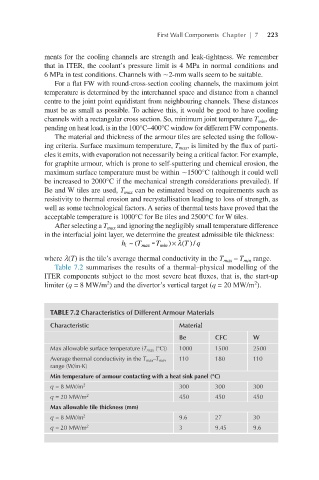
Table 7.2 summarises the results of a thermal–physical modelling of the
ITER components subject to the most severe heat fluxes, that is, the start-up
2
2
limiter (q = 8 MW/m ) and the divertor’s vertical target (q = 20 MW/m ).
TABLE 7.2 Characteristics of Different Armour Materials
Characteristic Material
Be CFC W
Max allowable surface temperature (T max (°С)) 1000 1500 2500
Average thermal conductivity in the T max –T min 110 180 110
range (W/m·K)
Min temperature of armour contacting with a heat sink panel (°C)
q = 8 MW/m 2 300 300 300
q = 20 MW/m 2 450 450 450
Max allowable tile thickness (mm)
q = 8 MW/m 2 9.6 27 30
q = 20 MW/m 2 3 9.45 9.6