Page 278 - Fundamentals of Magnetic Thermonuclear Reactor Design
P. 278

Plasma Control System  Chapter | 8    257


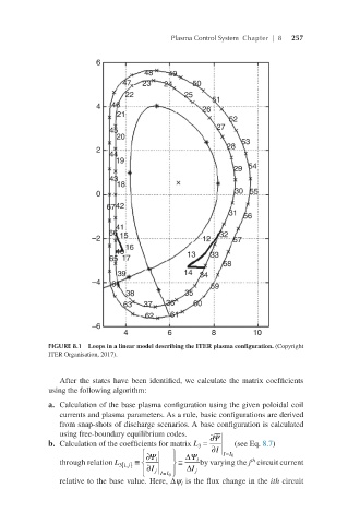
             FIGURE 8.1  Loops in a linear model describing the ITER plasma configuration. (Copyright
             ITER Organisation, 2017).


                After the states have been identified, we calculate the matrix coefficients
             using the following algorithm:
             a.  Calculation of the base plasma configuration using the given poloidal coil
                currents and plasma parameters. As a rule, basic configurations are derived
                from snap-shots of discharge scenarios. A base configuration is calculated
                using free-boundary equilibrium codes.  ∂ Ψ
             b.  Calculation of the coefficients for matrix L =  (see Eq. 8.7)                                      L =∂Ψ¯∂II=I 0
                                                  3
                                                                                                                     3
                                     ∂ Ψ     ∆ Ψ     I ∂  II 0
                                                         =
                                            
                                    
                                                               th
                through relation L 3, { ij}  ≡   i   ≅  i  by varying the j  circuit current                      L3i,j≡∂Ψi∂IjI=I ∆Ψi∆Ij
                                                                                                                                0
                                      I ∂  j  II 0   I ∆  j
                                            
                                    
                                         =
                relative to the base value. Here, ∆ψ  is the flux change in the ith circuit
                                              i
   273   274   275   276   277   278   279   280   281   282   283