
Page 258 - Fundamentals of Ocean Renewable Energy Generating Electricity From The Sea
P. 258
Optimization Chapter | 9 247
the reasoning behind the spacings is introduced here. Each tidal stream device
will generate a wake—a relatively narrow turbulent region downstream of the
device where the velocity is below ambient. Clearly, placement of a subsequent
device within this wake zone would lead to suboptimal device performance (e.g.
increased turbulence), and so not exploiting the resource to its full potential
(because the velocity in this region is below ambient). Therefore, the guidance
of spacing devices 10D in the longitudinal direction is designed to minimize
the wake effect. In addition, by staggering the devices, this will further prevent
a device positioned downstream of another device from operating in its wake
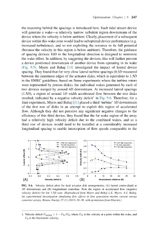
(Fig. 9.5). Myers and Bahaj [11] investigated the impact of lateral device
spacing. They found that for very close lateral turbine spacings (0.5D measured
between the innermost edges of the actuator disks, which is equivalent to 1.5D
in the EMEC guidelines; based on flume experiments where the turbine rotors
were represented by porous disks), the individual wakes generated by each of
two devices merged by around 4D downstream. At increased lateral spacings
(1.5D), a region of around 1D width accelerated flow between the two disks
1
resulted, indicated by a negative velocity deficit in Fig. 9.6. Therefore, for a
final experiment, Myers and Bahaj [11] placed a third ‘turbine’ 3D downstream
of the first row of disks in an attempt to exploit this region of accelerated
flow. Although they did not perceive any significant negative changes to the
efficiency of this third device, they found that the far wake region of the array
had a relatively high velocity deficit due to the combined wakes, and so a
third row of devices would need to be installed at a considerably increased
longitudinal spacing to enable interception of flow speeds comparable to the
4 0.5
0.5D disk separation 0.5D disk separation
1D disk separation 1D disk separation
1.5D disk separation 0.4 1.5D disk separation
2 0.3
Lateral offset (D) 0 Velocity deficit () 0.2
0.1
−2
0.0
−4 −0.1
−0.2 0.0 0.2 0.4 0.6 0.8 0 5 10 15 20 25 30
(A) Velocity deficit () (B) Downstream distance (D)
FIG. 9.6 Velocity deficit plots for dual actuator disk arrangements; (A) lateral centre-depth at
3D downstream and (B) longitudinal centreline. Note the region of accelerated flow (negative
velocity deficit) for the 1.5D case. (Reproduced from Myers and Bahaj L.E. Myers, A.S. Bahaj,
An experimental investigation simulating flow effects in first generation marine current energy
converter arrays, Renew. Energy 37 (1) (2012) 28–36, with permission from Elsevier.)
1. Velocity deficit U deficit = 1 − U w /U 0 ,where U w is the velocity at a point within the wake, and
U 0 is the freestream velocity.