
Page 162 - Fundamentals of Reservoir Engineering
P. 162
DARCY'S LAW AND APPLICATIONS 101
constant rate
water injection
q cc/sec
sand
l mercury
pack
manometers h 1
water collection h
and measurement 2
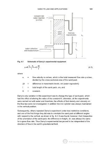
Fig. 4.1 Schematic of Darcy's experimental equipment
h − h ∆ h
uK 1 2 = K (4.1)
=
I I
where
u = flow velocity in cm/sec, which is the total measured flow rate q cc/sec,
divided by the cross-sectional area of the sand pack
∆h = difference in manometric levels, cm (water equivalent)
I = total length of the sand pack, cm, and
K = constant.
Darcy's only variation in this experiment was to change the type of sand pack, which
had the effect of altering the value of the constant K; otherwise, all the experiments
were carried out with water and therefore, the effects of fluid density and viscosity on
the flow law were not investigated. In addition the iron cylinder was always maintained
in the vertical position.
Subsequently, others repeated Darcy's experiment under less restrictive conditions,
and one of the first things they did was to orientate the sand pack at different angles
with respect to the vertical, as shown in fig. 4.2. It was found, however, that irrespective
of the orientation of the sand pack, the difference in height, ∆h, was always the same
for a given flow rate. Thus Darcy's experimental law proved to be independent of the
direction of flow in the earth's gravitational field.