
Page 219 - Fundamentals of Reservoir Engineering
P. 219
OILWELL TESTING 157
− initial pressure (p i)
− average pressure within the drainage boundary (p)
− permeability thickness product (kh), and permeability (k)
− mechanical skin factor (S)
− area drained (A)
− Dietz shape factor (C A)
In the following example of a pressure drawdown test, a well is produced at a single
constant rate from a known initial equilibrium pressure p i and p wf analysed as a function
of the flowing time t. Equation (7.10) is used to determine k and S while equ. (7.13) is
used for large values of t to determine A and C A. This latter part of the test is
sometimes referred to as reservoir limit testing and the analysis technique used to
2
determine the shape factor follows that presented by Earlougher .
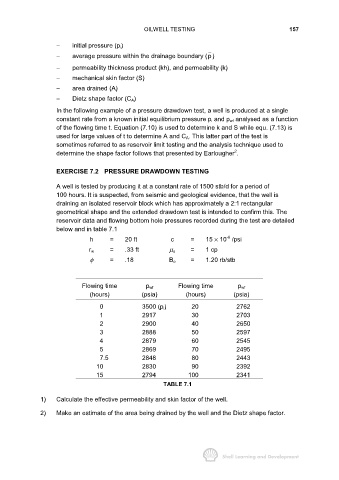
EXERCISE 7.2 PRESSURE DRAWDOWN TESTING
A well is tested by producing it at a constant rate of 1500 stb/d for a period of
100 hours. It is suspected, from seismic and geological evidence, that the well is
draining an isolated reservoir block which has approximately a 2:1 rectangular
geometrical shape and the extended drawdown test is intended to confirm this. The
reservoir data and flowing bottom hole pressures recorded during the test are detailed
below and in table 7.1
-6
h = 20 ft c = 15 × 10 /psi
= .33 ft = 1 cp
r w µ o
φ = .18 B o = 1.20 rb/stb
Flowing time p wf Flowing time p wf
(hours) (psia) (hours) (psia)
0 3500 (p i) 20 2762
1 2917 30 2703
2 2900 40 2650
3 2888 50 2597
4 2879 60 2545
5 2869 70 2495
7.5 2848 80 2443
10 2830 90 2392
15 2794 100 2341
TABLE 7.1
1) Calculate the effective permeability and skin factor of the well.
2) Make an estimate of the area being drained by the well and the Dietz shape factor.