
Page 184 - Fundamentals of The Finite Element Method for Heat and Fluid Flow
P. 184
176
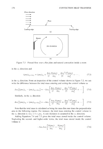
Flow direction
Plate CONVECTION HEAT TRANSFER
Leading edge Trailing edge
(a)
Heater
Air circulation
(b)
Figure 7.3 Forced flow over a flat plate and natural convection inside a room
in the x 1 direction and
2 2
x 2 ∂(ρu 2 ) x 2 ∂ (ρu 2 )
+ + + ··· . (7.3)
(ρu 2 ) x 2 + x 2 = (ρu 2 ) x 2
1! ∂x 2 2! ∂x 2
2
in the x 2 direction. From an inspection of the control volume shown in Figure 7.2, we can
write the difference between the total mass entering and exiting the control volume as
2 2
x 1 ∂(ρu 1 ) x 1 ∂ (ρu 1 )
x 2 (ρu 1 ) x 1 − (ρu 1 ) x 1 + x 1 =− x 2 + 2 + ··· (7.4)
1! ∂x 1 2! ∂x
1
Similarly, in the x 2 direction
2 2
x 2 ∂(ρu 2 ) x 2 ∂ (ρu 2 )
=− x 1 + + ··· (7.5)
x 1 (ρu 2 ) x 2 − (ρu 2 ) x 2 + x 2 2
1! ∂x 2 2! ∂x
2
Note that the total mass is calculated as being the mass flux rate times the perpendicular
area to the following regime. For instance, the total mass entering the control volume in
the x 1 direction is x 2 × 1 × ρu 1 . A unit thickness is assumed in the x 3 direction.
Adding Equations 7.4 and 7.5 gives the total mass stored inside the control volume.
Neglecting the second- and higher-order terms, the total mass stored inside the control
volume is
∂(ρu 1 ) ∂(ρu 2 )
− x 1 x 2 + (7.6)
∂x 1 ∂x 2