
Page 655 - Fundamentals of Water Treatment Unit Processes : Physical, Chemical, and Biological
P. 655
610 Fundamentals of Water Treatment Unit Processes: Physical, Chemical, and Biological
(a) (b)
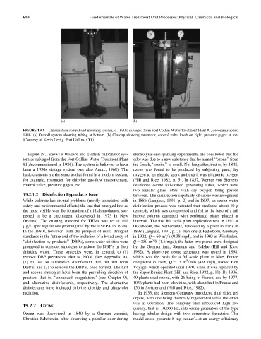
FIGURE 19.1 Chlorination control and metering system, c. 1930s; salvaged from Fort Collins Water Treatment Plant #1, decommissioned
1986. (a) Overall system showing tubing at bottom. (b) Closeup showing rotometer, control valve knob on right, pressure gages at top.
(Courtesy of Kevin Gertig, Fort Collins, CO.)
Figure 19.1 shows a Wallace and Tiernan chlorinator sys- electrolysis-and-sparking experiments. He concluded that the
tem as salvaged from the Fort Collins Water Treatment Plant odor was due to a new substance that he named ‘‘ozone’’ from
#1(decommissioned in 1986). The system is believed to have the Greek, ‘‘ozein,’’ to smell. Not long after, that is, by 1848,
been a 1930s vintage system (see also Anon., 1968). The ozone was found to be produced by subjecting pure, dry
basic elements are the same as that found in a modern system, oxygen to an electric spark and that it was tri-atomic oxygen
for example, rotometer for chlorine gas-flow measurement, (Hill and Rice, 1982, p. 5). In 1857, Werner von Siemens
control valve, pressure gages, etc. developed ozone foil-coated generating tubes, which were
two annular glass tubes, with dry oxygen being passed
19.2.1.2 Disinfection Byproducts Issue between. The disinfection capability of ozone was recognized
While chlorine has several problems (mostly associated with in 1886 (Langlais, 1991, p. 2) and in 1897, an ozone water
safety and environmental effects) the one that emerged first as disinfection process was patented that produced about 10 g
the most visible was the formation of tri-halomethanes, sus- ozone=h, which was compressed and fed to the base of a tall
pected to be a carcinogen (discovered in 1973 in New bubble column equipped with perforated plates placed at
Orleans). The ensuing standard for THMs was set at 100 intervals. The first full scale plant application was in 1893 at
mg=L (per regulations promulgated by the USEPA in 1978). Oudshoorn, the Netherlands, followed by a plant in Paris in
In the 1980s, however, with the prospect of more stringent 1898 (Langlais, 1991, p. 2), then one at Paderborn, Germany
3
standards in the future and of the inclusion of a broad array of in 1902, Q ¼ 60 m =h (0.38 mgd), and in 1903 at Wiesbaden,
3
‘‘disinfection by-products’’ (DBPs), some water utilities were Q ¼ 250 m =h (1.6 mgd); the latter two plants were designed
prompted to consider strategies to reduce the DBP’s in their by the German firm, Siemens and Halske (Hill and Rice,
drinking water. These strategies were, in general, to (1) 1982). A plate-type ozone generator was tested in 1898,
remove DBP precursors, that is, NOM (see Appendix A), which was the basis for a full-scale plant at Nice, France
3
(2) to use an alternative disinfectant that did not form completed in 1906, Q ¼ 13 m =min (4.9 mgd), named Bon
DBP’s, and (3) to remove the DBP’s, once formed. The first Voyage, which operated until 1970, when it was replaced by
and second strategies have been the prevailing direction of the Super Rimiez Plant (Hill and Rice, 1982, p. 11). By 1906,
practice, that is, ‘‘enhanced coagulation’’ (see Chapter 9), 49 plants used ozone, with 26 being in France, and by 1977,
and alternative disinfectants, respectively. The alternative 1036 plants had been identified, with about half in France and
disinfectants have included chlorine dioxide and ultraviolet 150 in Switzerland (Hill and Rice, 1982).
radiation. In 1933, the Siemens Company introduced dual silica gel
dryers, with one being thermally regenerated while the other
was in operation. The company also introduced high fre-
19.2.2 OZONE
quency, that is, 10,000 Hz, into ozone generators of the type
Ozone was discovered in 1840 by a German chemist, having tubular design with two concentric dielectrics. The
Christian Schönbein, after observing a peculiar odor during model could generate 8 mg ozone=L at an energy efficiency