
Page 254 - Geotechnical Engineering Soil and Foundation Principles and Practice
P. 254
Soil Consistency and Engineering Classification
Soil Consistency and Engineering Classification 249
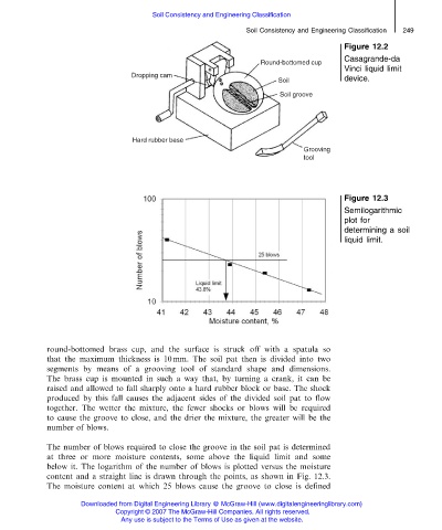
Figure 12.2
Casagrande-da
Vinci liquid limit
device.
Figure 12.3
Semilogarithmic
plot for
determining a soil
liquid limit.
round-bottomed brass cup, and the surface is struck off with a spatula so
that the maximum thickness is 10 mm. The soil pat then is divided into two
segments by means of a grooving tool of standard shape and dimensions.
The brass cup is mounted in such a way that, by turning a crank, it can be
raised and allowed to fall sharply onto a hard rubber block or base. The shock
produced by this fall causes the adjacent sides of the divided soil pat to flow
together. The wetter the mixture, the fewer shocks or blows will be required
to cause the groove to close, and the drier the mixture, the greater will be the
number of blows.
The number of blows required to close the groove in the soil pat is determined
at three or more moisture contents, some above the liquid limit and some
below it. The logarithm of the number of blows is plotted versus the moisture
content and a straight line is drawn through the points, as shown in Fig. 12.3.
The moisture content at which 25 blows cause the groove to close is defined
Downloaded from Digital Engineering Library @ McGraw-Hill (www.digitalengineeringlibrary.com)
Copyright © 2007 The McGraw-Hill Companies. All rights reserved.
Any use is subject to the Terms of Use as given at the website.