
Page 112 - HVAC Pump Handbook
P. 112
Rishel_CH05.qxd 21/4/06 6:12 PM Page 109
Physical Description of HVAC Pumps
Physical Description of HVAC Pumps 109
describe these pumps, because water is diffused around the entire
periphery of the impeller and flows axially through the pump. There
is no volute to collect the water from the impeller. Instead, the
impeller is housed in a bowl assembly that has a suction connection
and a discharge section. Water enters the pump bowl and passes
through the impeller and the bowl vanes to the discharge connection.
With this arrangement, it is very easy to make up these pumps in
what is called stages. A two-stage pump merely indicates that two
bowls and impellers are installed in series together, as shown in
Fig. 4.2d. How pumps operate in series or parallel is described in
detail in Chap. 6.
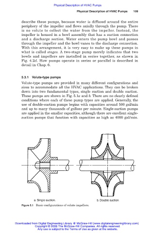
5.3.1 Volute-type pumps
Volute-type pumps are provided in many different configurations and
sizes to accommodate all the HVAC applications. They can be broken
down into two fundamental types, single suction and double suction.
These pumps are shown in Fig. 5.1a and b. There are no clearly defined
conditions where each of these pump types are applied. Generally, the
use of double-suction pumps begins with capacities around 500 gal/min
and up to many thousands of gallons per minute. Single-suction pumps
are applied in the smaller capacities, although there are excellent single-
suction pumps that function with capacities as high as 4000 gal/min.
Figure 5.1 Basic configurations of volute impellers.
Downloaded from Digital Engineering Library @ McGraw-Hill (www.digitalengineeringlibrary.com)
Copyright © 2006 The McGraw-Hill Companies. All rights reserved.
Any use is subject to the Terms of Use as given at the website.