
Page 85 - HVAC Pump Handbook
P. 85
Rishel_CH03.qxd 20/4/06 5:35 PM Page 82
Piping System Friction
82 The Basic Tools
nodes must indicate elevations above sea level to demonstrate changes
in static pressure.
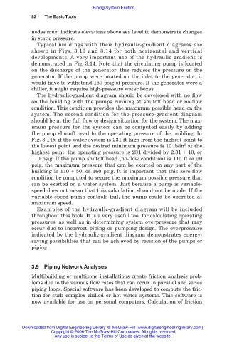
Typical buildings with their hydraulic-gradient diagrams are
shown in Figs. 3.13 and 3.14 for both horizontal and vertical
developments. A very important use of the hydraulic gradient is
demonstrated in Fig. 3.14. Note that the circulating pump is located
on the discharge of the generator; this reduces the pressure on the
generator. If the pump were located on the inlet to the generator, it
would have to withstand 160 psig of pressure. If the generator were a
chiller, it might require high-pressure water boxes.
The hydraulic-gradient diagram should be developed with no flow
on the building with the pumps running at shutoff head or no-flow
condition. This condition provides the maximum possible head on the
system. The second condition for the pressure-gradient diagram
should be at the full flow or design situation for the system. The max-
imum pressure for the system can be computed easily by adding
the pump shutoff head to the operating pressure of the building. In
Fig. 3.14b, if the water system is 231 ft high from the highest point to
2
the lowest point and the desired minimum pressure is 10 lb/in at the
highest point, the operating pressure is 231 divided by 2.31 10, or
110 psig. If the pump shutoff head (no-flow condition) is 115 ft or 50
psig, the maximum pressure that can be exerted on any part of the
building is 110 50, or 160 psig. It is important that this zero-flow
condition be computed to secure the maximum possible pressure that
can be exerted on a water system. Just because a pump is variable-
speed does not mean that this calculation should not be made. If the
variable-speed pump controls fail, the pump could be operated at
maximum speed.
Examples of the hydraulic-gradient diagram will be included
throughout this book. It is a very useful tool for calculating operating
pressures, as well as in determining system overpressure that may
occur due to incorrect piping or pumping design. The overpressure
indicated by the hydraulic-gradient diagram demonstrates energy-
saving possibilities that can be achieved by revision of the pumps or
piping.
3.9 Piping Network Analyses
Multibuilding or multizone installations create friction analysis prob-
lems due to the various flow rates that can occur in parallel and series
piping loops. Special software has been developed to compute the fric-
tion for such complex chilled or hot water systems. This software is
now available for use on personal computers. Calculation of friction
Downloaded from Digital Engineering Library @ McGraw-Hill (www.digitalengineeringlibrary.com)
Copyright © 2006 The McGraw-Hill Companies. All rights reserved.
Any use is subject to the Terms of Use as given at the website.