
Page 342 - Handbook of Battery Materials
P. 342
312 11 Separators
2
The electrical resistance, at 60–90 m cm , is astonishingly low, because the
backweb is only 0.25–0.30 mm thick and the glass mat with its porosity in excess of
90% also contributes only a little. In some types of construction the low electrical
resistance cannot be fully utilized, however, due to a tendency for gas to be trapped
within the glass mat.
The oxidative stability is excellent. Direct contact between the glass mat and the
positive electrode produces a far lower tendency to shed active mass; thus as a
general rule the failure mode is positive grid corrosion.
It is rather difficult to compare constructions differing to such an extent, since
in the course of development the standards and also the electric layout of vehicles
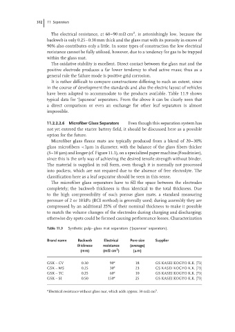
have been adapted to accommodate to the products available. Table 11.9 shows
typical data for ‘Japanese’ separators. From the above it can be clearly seen that
a direct comparison or even an exchange for other leaf separators is almost
impossible.
11.2.2.2.6 Microfiber Glass Separators Even though this separation system has
not yet entered the starter battery field, it should be discussed here as a possible
option for the future.
Microfiber glass fleece mats are typically produced from a blend of 20–30%
glass microfibers <1µm in diameter, with the balance of the glass fibers thicker
(3–10 µm) and longer (cf. Figure 11.1), on a specialized paper machine (Foudrinier),
since this is the only way of achieving the desired tensile strength without binder.
The material is supplied in roll form, even though it is normally not processed
into pockets, which are not required due to the absence of free electrolyte. The
classification here as a leaf separator should be seen in this sense.
The microfiber glass separators have to fill the space between the electrodes
completely; the backweb thickness is thus identical to the total thickness. Due
to the high compressibility of such porous glass mats, a standard measuring
pressure of 2 or 10 kPa (BCI method) is generally used; during assembly they are
compressed by an additional 25% of their nominal thickness to make it possible
to match the volume changes of the electrodes during charging and discharging;
otherwise dry spots could be formed causing performance losses. Characterization
Table 11.9 Synthetic pulp–glass mat separators (‘Japanese’ separators).
Brand name Backweb Electrical Pore size Supplier
thickness resistance (average)
2
(mm) (mΩ cm ) (µm)
GSK – CV 0.30 90 a 18 GS KASEI KOGYO K.K. [73]
GSK – MS 0.25 30 a 23 GS KASEI KOGYO K.K. [73]
GSK – TC 0.25 60 a 10 GS KASEI KOGYO K.K. [73]
GSK – SI 0.50 150 a 25 GS KASEI KOGYO K.K. [73]
a 2
Electrical resistance without glass mat, which adds approx. 30 m cm .