Page 117 - Handbook of Biomechatronics
P. 117

Model-Based Control of Biomechatronic Systems                113


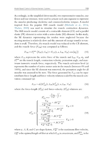
              Accordingly, in the simplified driver model, two representative muscles, one
              flexor and one extensor, were used to actuate each arm segment to represent
              the muscles producing clockwise and counterclockwise torques. A model
              inspired from the popular Hill muscle model (Mehrabi et al., 2014;
              Thelen, 2003) was used to simulate the muscle contraction dynamics.
              The Hill muscle model consists of a contractile element (CE) and a parallel
              elastic (PE) element in series with a series elastic (SE) element. In this study,
              the SE dynamics representing the tendon were neglected because the
              steering motion is relatively slow and the amount of energy transfer to ten-
              dons is small. Therefore, the muscle model was reduced to the CE element,
              and the muscle force (F TM ) was computed as follows:

                      F TM ¼ F max     ð         ð                         (15)
                              0   F PE t, L M Þ + F CE t, a, L M , V M Þ cos α p
              where F CE represents the active force of the muscle and L M , V M , α p , and
               max
              F 0  are the muscle length, contraction velocity, pennation angle, and max-
              imum isometric muscle force, respectively. The muscle activation level (a)
              represents the number of active motor units in the muscle (between 0% and
              100%), and since the SE element was removed, the pennation angle for all
              muscles was assumed to be zero. The force generated by F CE can be sepa-
              rated into force-length and force-velocity relations scaled by the muscle acti-
              vation command (a):

                             F CE ¼ atðÞF L  ð t, L M ÞF V  ð t, a, L M , V M Þ  (16)
                                       CE        CE
                                    L                     V
              where the force-length (F CE ) and force-velocity (F CE ) relations are:
                                                     2
                                               L M
                                       L       L opt 1  =γ
                                     F   ¼ e   M                           (17)
                                       CE
                                8
                                        V M        max
                                >             + AV
                                >      max  opt    M
                                     V    L
                                >
                                >      M   M
                                >
                                >                         V M < 0
                                >
                                         V M
                                >                    max
                                                + AV
                                >
                                >
                                >      max  opt      M
                                <    V M  L M  A f
                           F V  ¼         len                              (18)
                            CE      V M BF
                                >         max       max
                                >             + ACV
                                >     max  opt      M
                                     V   L
                                >
                                >
                                >     M    M
                                >                         V M > 0
                                       V M B
                                >
                                >
                                >                     max
                                >              + ACV
                                :     max  opt        M
                                    V
                                      M  L A f
                                          M
                                                 max
              where γ, A, B, and C are shape factors, V M is the maximum fiber velocity,
               opt
              L M is the optimal length of fiber at which F CE is a maximum, and F len  is the
                                                                       max
   112   113   114   115   116   117   118   119   120   121   122