
Page 583 - Handbook of Biomechatronics
P. 583
Pacemakers 575
coil about 250mm in diameter taped to the patient’s abdomen. Recharging
was accomplished weekly for 12h using a 150-kHz radio frequency vacuum
tube oscillator that fed the external coil.
The unit was entirely handmade and consisted of the batteries, the elec-
tronic circuit, and the charging coil encapsulated in a new epoxy resin
(Araldite) produced by Ciba-Geigy, which had been found to have excellent
biocompatibility properties. The approximate diameter and thickness,
55 and 16mm, respectively, were determined by the dimensions of a Kiwi
shoe polish tin in which the device was cast. A photograph of a reproduction
of the device and the circuit diagram are shown in Fig. 4.
The patient suffered from Stokes-Adams attacks that required resuscita-
tion many times daily and his situation was considered hopeless. The
implantation was a desperate measure and very risky. The first prototype
failed within 8h and the second started to fail within a week, but everyone
persevered and in the end the patient outlived them all, having survived
25 pacemaker changes.
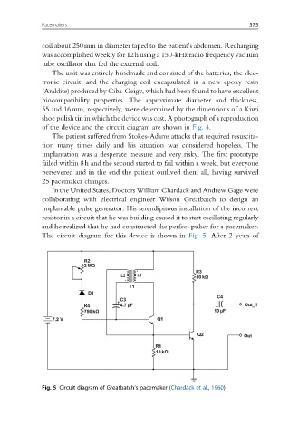
In the United States, Doctors William Chardack and Andrew Gage were
collaborating with electrical engineer Wilson Greatbatch to design an
implantable pulse generator. His serendipitous installation of the incorrect
resistor in a circuit that he was building caused it to start oscillating regularly
and he realized that he had constructed the perfect pulser for a pacemaker.
The circuit diagram for this device is shown in Fig. 5. After 2 years of
Fig. 5 Circuit diagram of Greatbatch’s pacemaker (Chardack et al., 1960).