
Page 277 - Handbook of Electronic Assistive Technology
P. 277
266 HANDBOOK OF ELECTRONIC ASSISTIVE TECHNOLOGY
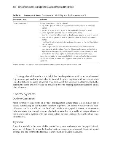
Table 9-1 Assessment Areas for Powered Mobility and Rationale—cont’d
Assessment Area Rationale
Linear measurements Linear measurements must be taken of:
• Hip width: greater trochanter to greater trochanter (coronal or transverse
planes).
• Sacrum to within around 10 mm of the popliteal fossa (sagittal plane).
• Lower leg length: popliteal fossa to heel (sagittal plane).
• Shoulder height: ischial tuberosity to distal clavicle (sagittal or coronal planes).
• Shoulder width: greater tubercle to greater tubercle (coronal or transverse
planes).
• Head height: ischial tuberosity to most superior aspect of the skull (sagittal or
coronal planes).
• Elbow height: with the shoulder in neutral ab/adduction and extension/
elevation, and with the elbow flexed to 90 degrees from seat surface (ischial
tuberosity) to olecranon process of the ulna (sagittal plane).Allowances may
be needed in the foregoing for musculature and/or excess soft tissues.
It may also be helpful to measure axilla height to seat surface/ischial tuberosity
in the coronal plane, if lateral trunk supports are required to aid postural
alignment.
Adapted from MPD 24/7, Oxford Centre for Enablement, Oxford University Hospitals NHS Foundation Trust.
Having gathered these data, it is helpful to list the problems which can be addressed
(e.g., cannot get under a table due to joystick height), together with any constraints
(e.g., limitations in space at home). This will assist the assessor in clarifying with the
person the aims and objectives of provision prior to making recommendations and a
plan of action.
Control Systems
Outline Operation
Most control systems work on a ‘bus’ configuration where there is a common set of
cables connecting all the different modules together. The modules all listen and con-
tribute to the data traffic on the ‘bus’ and this is how a joystick passes its movement
information to the control system, which then uses this to provide an output either to
the motor control system or to the other output devices that may be on the chair (e.g.,
tilt actuator).
Joysticks
A joystick module is the most visible part of the system and comprises the joystick itself,
some sort of display to show the level of battery charge, operation and display of speed
settings and the control of additional features such as tilt, rise, stand, etc.