
Page 206 - High Power Laser Handbook
P. 206
174 So l i d - S t at e La s e r s Intr oduction to High-Power Solid-State Lasers 175
All HAP SSL designs require some means of managing the impact of
thermal gradients on the extracting laser beam’s wavefront. There are
two geometric considerations here.
The first consideration is to select a cooling geometry that mini-
mizes the magnitude of the thermal gradients themselves. This leads
to a gain material shape with a large surface area for heat removal, so
that the surface heat flux is minimized. Furthermore, reducing the
thickness of the gain material along the direction normal to the cool-
ing surface will reduce the temperature rise. Hence, the desire to
minimize thermal gradients in SSLs invariably leads to high-aspect
ratio structures.
The second consideration is to select a laser extraction geometry
that has little or no sensitivity to thermal gradients—in particular,
one in which the extracting laser beam propagates with a vector com-
ponent aligned with the primary thermal gradient. As an example,
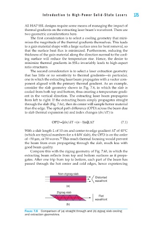
consider the slab geometry shown in Fig. 7.6, in which the slab is
cooled from both top and bottom, thus creating a temperature gradi-
ent in the vertical direction. The extracting laser beam propagates
from left to right. If the extracting beam simply propagates straight
through the slab (Fig. 7.6a), then its center will sample hotter material
than the edge. The optical path difference (OPD) across the beam due
to slab thermal expansion (α) and index changes (dn/dT) is
α∆
OPD = /dT + [dn (n − )]L T (7.1)
1
With a slab length L of 10 cm and center-to-edge gradient ∆T of 40°C
(which are typical numbers for a 4-kW slab), the OPD is on the order
of ~50 µm, or 50 waves. This much thermal focusing would prevent
20
the beam from even propagating through the slab, much less with
good beam quality.
Compare this with the zigzag geometry of Fig. 7.6b, in which the
extracting beam reflects from top and bottom surfaces as it propa-
gates. After one trip from top to bottom, each part of the beam has
passed through the hot center and cold edges, hence experiencing
Non-zigzag slab
Distorted
wavefront
(a)
Zigzag slab
Flat
wavefront
(b)
Figure 7.6 Comparison of (a) straight-through and (b) zigzag slab cooling
and extraction geometries.