
Page 515 - High Power Laser Handbook
P. 515
482 Fi b er L a s er s Pulsed Fiber Lasers 483
1.2
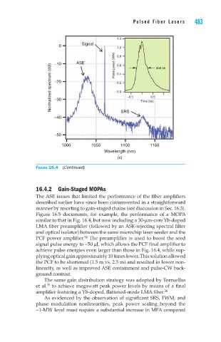
0 Signal 1.0
−10 ASE Pulse power (MW) 0.8 450 ps
Normalized spectrum (dB) −20 0.2 −0.5 Time (ns)
0.6
0.4
0.0
0.5
−30
−40 SRS
−50
1000 1050 1100 1150
Wavelength (nm)
(c)
Figure 16.4 (Continued)
16.4.2 Gain-Staged MOPAs
The ASE issues that limited the performance of the fiber amplifiers
described earlier have since been circumvented in a straightforward
manner by resorting to gain-staged chains (see discussion in Sec. 16.3).
Figure 16.5 documents, for example, the performance of a MOPA
similar to that in Fig. 16.4, but now including a 30-μm-core Yb-doped
LMA fiber preamplifier (followed by an ASE-rejecting spectral filter
and optical isolator) between the same microchip laser seeder and the
PCF power amplifier. The preamplifier is used to boost the seed
34
signal pulse energy to ~50 μJ, which allows the PCF final amplifier to
achieve pulse energies even larger than those in Fig. 16.4, while sup-
plying optical gain approximately 10 times lower. This solution allowed
the PCF to be shortened (1.5 m vs. 2.5 m) and resulted in lower non-
linearity, as well as improved ASE containment and pulse-CW back-
ground contrast.
The same gain distribution strategy was adopted by Torruellas
et al. to achieve megawatt peak power levels by means of a final
35
amplifier featuring a Yb-doped, flattened-mode LMA fiber.
36
As evidenced by the observation of significant SRS, FWM, and
phase modulation nonlinearities, peak power scaling beyond the
~1-MW level must require a substantial increase in MFA compared