
Page 74 - High Power Laser Handbook
P. 74
Cavity nozzle blades X10
top view
D 2 + He
H 2 O
+ F + He
CF 4 + HF
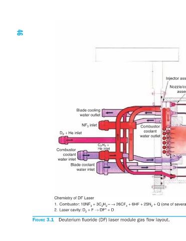
Injector assembly Module Nozzle/combustor assembly Mixing/reaction assembly region D 2 + F → DF* + D CF 4 + HF + F + He Lasing cavity Gas flow Pressure recovery diffuser inlet Shroud Optical axis 1. Combustor: 10NF 3 + 3C 2 H 2 – → 26CF 4 + 6HF + 25N 2 + Q (one of several reactions us
Combustor coolant water outlet
C 2 H 2 + He inlet Deuterium fluoride (DF) laser module gas flow layout.
Blade cooling water outlet NF 3 inlet Blade coolant water inlet 2. Laser cavity: D 2 + F → DF* + D
D 2 + He inlet Combustor coolant water inlet Chemistry of DF Laser
Figure 3.1
46