
Page 19 - Human Inspired Dexterity in Robotic Manipulation
P. 19
Digital Hand: Interface Between the Robot Hand and Human Hand 15
2.2.2 Link and Joint of the Digital Hand
The digital-hand model consists of a surface mesh, explained in the next
section, for visualizing the surface geometry and a link structure for control-
ling the posture and movement of the hand. As we reviewed in the previous
section, the control of hand motion by the musculoskeletal structure is com-
plicated, because the movement of one specific joint is produced by more
than one muscle, and one specific muscle is contributing to the movements
of several joints.
To simplify the control of hand motion, the link structure of the digital-
hand model has fewer degrees of freedom (DoF) than those of the human
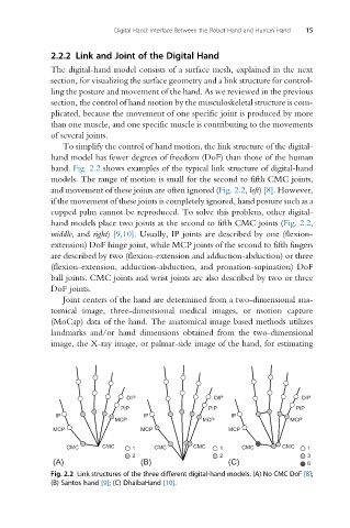
hand. Fig. 2.2 shows examples of the typical link structure of digital-hand
models. The range of motion is small for the second to fifth CMC joints,
and movement of these joints are often ignored (Fig. 2.2, left) [8]. However,
if the movement of these joints is completely ignored, hand posture such as a
cupped palm cannot be reproduced. To solve this problem, other digital-
hand models place two joints at the second to fifth CMC joints (Fig. 2.2,
middle, and right) [9,10]. Usually, IP joints are described by one (flexion-
extension) DoF hinge joint, while MCP joints of the second to fifth fingers
are described by two (flexion-extension and adduction-abduction) or three
(flexion-extension, adduction-abduction, and pronation-supination) DoF
ball joints. CMC joints and wrist joints are also described by two or three
DoF joints.
Joint centers of the hand are determined from a two-dimensional ana-
tomical image, three-dimensional medical images, or motion capture
(MoCap) data of the hand. The anatomical image based methods utilizes
landmarks and/or hand dimensions obtained from the two-dimensional
image, the X-ray image, or palmar-side image of the hand, for estimating
DIP DIP DIP
PIP PIP PIP
IP IP IP
MCP MCP MCP
MCP MCP MCP
CMC CMC 1 CMC CMC 1 CMC CMC 1
2 2 3
(A) (B) (C) 6
Fig. 2.2 Link structures of the three different digital-hand models. (A) No CMC DoF [8];
(B) Santos hand [9]; (C) DhaibaHand [10].