
Page 31 - Hybrid-Renewable Energy Systems in Microgrids
P. 31
16 Hybrid-Renewable Energy Systems in Microgrids
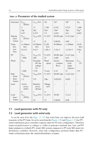
Table 1.4 Parameter of the studied system
Generator P nom V L-L (kV) Xd Xd′ Xd″ Xq
(MVA)
5 13 1.790 0.355 0.275 1.660
Xq’ Xq” Tdo′ Tdo″ Tqo′ Tqo″
0.57 0.275 7.9 0.032 0.41 0.055
Step-up P nom V prim (kV) V s (kV) R1,R2 (pu) L1,L2 (pu) –
trans- (MVA)
former 5 13 25 0.08/30 0.08 –
Trans- r1 (Ohms/ r0 (Ohms/ l1 (H/ l0 (H/km) c1 (F/km) c0 (F/
mis- km) km) km) km)
sion 0.1153 0.413 1.05e-3 3.32e-3 11.33e-9 5.01e-
lines 9
PV P nom V prim (V) V s (kV) R1,R2 (pu) L1,L2 (pu) –
1 MW 260 25 0.001 0.03 –
Wind P nom Nominal Wind Inertia Maximum V L-L
DC bus speed constant pitch (V)
voltage H (s) angle
(V) (degree)
1 MW 1150 15 m/s 4.32 27 575
Step- P nom V prim (kV) V s (kV) R1,R2 (pu) L1,L2 (pu) –
down (MVA)
trans- 1.2 575 25kv 0.025/30 0.025 –
former
Load Active Reactive Voltage – – –
power power (kV)
(MW) (MVar)
6 1 11 – – –
Load P nom V prim (kV) V s (kV) R1,R2 L1,L2 –
trans- (MVA)
former 8 25 13 0.08/30 0.08 –
7.1 Load generator with PV only
7.2 Load generator with wind only
It can be seen from the Figs. 1.7–1.9 that wind farm can improve the post-fault
transients of the PV farm. It can be seen from the Figure 1.10 and Figure 1.11 that PV–
wind combination gives smoother response than the PV-only configuration. Therefore
improved performance in voltages is visible at generator terminal, bus, load, and PV
farm terminal in a hybrid (PV–wind) MG system compared to PV-only MG under the
disturbance condition. However, wind-only configuration performs better than PV–
wind combination under the studied disturbance scenario.