
Page 112 - Hydrocarbon
P. 112
Reservoir Description 99
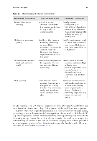
Table 6.1 Characteristics of selected environments
Depositional Environment Reservoir Distribution Production Characteristic
Deltaic (distributary Isolated or stacked Good producers;
channel) channels usually with permeabilities of
fine-grained sands. May 500–5000 mD. Insufficient
or may not be in communication between
communication channels may require infill
wells in late stage of
development
Shallow marine/coastal Sand bars, tidal channels. Prolific producers as a result
(clastic) Generally coarsening of ‘clean’ and continuous
upwards. High sand bodies. Shale layers
subsidence rate results in may cause vertical barriers
‘stacked’ reservoirs. to fluid flow
Reservoir distribution
dependent on wave and
tide action
Shallow water carbonate Reservoir quality governed Prolific production from
(reefs and carbonate by diagenetic processes karstified carbonates. High
muds) and structural history and early water
(fracturing) production possible. ‘Dual
porosity’ systems in
fractured carbonates.
Dolomites may produce
H 2 S
Shelf (clastics) Sheet-like sand bodies Very high productivity but
resulting from storms or high-quality sands may act
transgression. Usually as ‘thief zones’ during
thin but very continuous water or gas injection.
sands, well sorted and Action of sediment
coarse between marine burrowing organisms may
clays impact on reservoir
quality
to GR response. The GR response measures the level of natural GR activity in the
rock formation. Shales have a high GR response, whilst sands have low responses.
A funnel-shaped GR log is often indicative of a deltaic environment whereby clastic,
increasingly coarse sedimentation follows deposition of marine clays. Bell-shaped GR
logs often represent a channel environment where a fining upwards sequence reflects
decreasing energy across the vertical channel profile. A modern technique for
sedimentological studies is the use of formation imaging tools which provide a
very high quality picture of the formations forming the borehole wall. These are
described in more detail in Section 6.4.8.